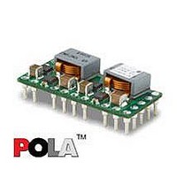
PMN5118UP Ericsson Power Modules, PMN5118UP Datasheet - Page 26

PMN5118UP
Manufacturer Part Number
PMN5118UP
Description
DC/DC Converters & Regulators 0.7-3.6V 30A Non-Iso Input 4.5-5.5V 108W
Manufacturer
Ericsson Power Modules
Series
PMNr
Datasheet
1.PMN5118USR.pdf
(37 pages)
Specifications of PMN5118UP
Output Power
108 W
Input Voltage Range
4.5 V to 5.5 V
Number Of Outputs
1
Output Voltage (channel 1)
0.7 V to 3.6 V
Output Current (channel 1)
30 A
Output Type
POLA Non-Isolated Regulator
Product
Non-Isolated / POL
Lead Free Status / RoHS Status
Lead free / RoHS Compliant
Available stocks
Company
Part Number
Manufacturer
Quantity
Price
Part Number:
PMN5118UP
Manufacturer:
ERICSSON/爱立信
Quantity:
20 000
E
EMC Specification
Conducted EMI measured according to test set-up.
The fundamental switching frequency is 640 kHz for
PMN 5118U P @ V
Conducted EMI Input terminal value (typ)
EMI without filter
Test set-up
Layout recommendation
The radiated EMI performance of the DC/DC regulator will
depend on the PCB layout and ground layer design.
It is also important to consider the stand-off of the DC/DC
regulator.
If a ground layer is used, it should be connected to the output
of the DC/DC regulator and the equipment ground or chassis.
A ground layer will increase the stray capacitance in the PCB
and improve the high frequency EMC performance.
Prepared (also subject responsible if other)
EYIPYAN
Approved
SEC/D (Julia You)
PMN 5000 series
POL regulator, Input 4.5-5.5 V, Output up to 30 A/108 W
I
= 5 V, max I
TBD
TBD
O
.
Checked
EQUENXU
Ericsson Internal
PRODUCT SPECIFICATION
No.
3/1301-BMR656 5118 Uen
Date
2007-7-9
Output ripple and noise
Output ripple and noise measured according to figure below.
See Design Note 022 for detailed information.
Output ripple and noise test setup
Operating information
Extended information for POLA products is found in
Application Note 205.
Input Voltage
The input voltage range 4.5 to 5.5 Vdc makes the product
easy to use in intermediate bus applications when powered
by a regulated bus converter.
Turn-off Input Voltage
The DC/DC regulators monitor the input voltage and will turn
on and turn off at predetermined levels.
The minimum hysteresis between turn on and turn off input
voltage is 0.1V.
Remote Control (RC) Inhibit
The maximum required sink current is 1 mA. When the RC pin
is left open, the voltage generated on the RC pin is
4.5-5.5 V. The regulator will turn on when the input voltage is
applied with the RC pin open. Turn off is achieved by
connecting the RC pin to the - In. To ensure safe turn off the
voltage difference between RC pin and the - In pin shall be
less than 1V. The regulator will restart automatically when this
connection is opened.
Technical Specification
EN/LZT 146 386 R1A
© Ericsson Power Modules AB
Rev
B
The products are fitted with a
remote control function referenced
to positive logic. The RC function
allows the regulator to be turned
on/off by an external device like a
semiconductor or mechanical
switch. The RC pin has an internal
pull up resistor to + In.
Reference
July 2007
1 (8)
26


