PMN5118UP Ericsson Power Modules, PMN5118UP Datasheet - Page 30
PMN5118UP
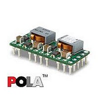
Manufacturer Part Number
PMN5118UP
Description
DC/DC Converters & Regulators 0.7-3.6V 30A Non-Iso Input 4.5-5.5V 108W
Manufacturer
Ericsson Power Modules
Series
PMNr
Datasheet
1.PMN5118USR.pdf
(37 pages)
Specifications of PMN5118UP
Output Power
108 W
Input Voltage Range
4.5 V to 5.5 V
Number Of Outputs
1
Output Voltage (channel 1)
0.7 V to 3.6 V
Output Current (channel 1)
30 A
Output Type
POLA Non-Isolated Regulator
Product
Non-Isolated / POL
Lead Free Status / RoHS Status
Lead free / RoHS Compliant
Available stocks
Company
Part Number
Manufacturer
Quantity
Price

Part Number:
PMN5118UP
Manufacturer:
ERICSSON/爱立信
Quantity:
20 000


E
R
The Turbo Trans
the Turbo Trans
below.
Where C
greater than or equal to 2350 µF require R
0Ω. (The above equation results in a negative value for R
≥ 2350 µF)
R
Prepared (also subject responsible if other)
EYIPYAN
Approved
SEC/D (Julia You)
PMN 5000 series
POL regulator, Input 4.5-5.5 V, Output up to 30 A/108 W
TT
TT
Resistor Selection
=
40
o
is the total output capacitance in µF. C
×
5
TM
1
×
TM
−
(
programming equation, see the equation
resistor value, R
2350
(
C
2350
C
o
o
)
−
)
1
(
k
Ω
TT
)
can be determined from
TT
to be a short,
Checked
EQUENXU
o
values
TT
when C
o
Thermal Consideration
General
The regulators are designed to operate in different thermal
environments and sufficient cooling must be provided to
ensure reliable operation.
Cooling is achieved mainly by conduction, from the pins to
the host board, and convection, which is dependant on the
airflow across the regulator. Increased airflow enhances the
cooling of the regulator.
The Output Current Derating graph found in the Output
section for each model provides the available output current
vs. ambient air temperature and air velocity at V
The DC/DC regulator is tested on a 254 x 254 mm,
35 µm (1 oz), 8-layer test board mounted vertically in a wind
tunnel with a cross-section of 305 x 305 mm.
Proper cooling of the DC/DC regulator can be verified by
measuring the temperature at positions P1, P2 and P3. The
temperature at these positions should not exceed the max
values provided in the table below.
Note that the max value is the absolute maximum rating
(non destruction) and that the electrical Output data is
guaranteed up to ambient temperature +85°C.
See Design Note 019 for further information.
Ericsson Internal
PRODUCT SPECIFICATION
No.
3/1301-BMR656 5118 Uen
Date
2007-7-9
Position
P
P
P
1
2
3
Device
Pcb
Mosfet
Inductor
Technical Specification
EN/LZT 146 386 R1A
© Ericsson Power Modules AB
Rev
B
Designation
T
ref
Reference
July 2007
max value
130º C
130º C
130º C
in
= 5 V.
5 (8)
30
Related parts for PMN5118UP
Image
Part Number
Description
Manufacturer
Datasheet
Request
R

Part Number:
Description:
37.5-150W DC/DC POWER MODULES
Manufacturer:
Ericsson Power Modules
Part Number:
Description:
DC/DC Power Supply Dual-OUT 3.3V/5V 9.6A/6.4A 40W 10-Pin
Manufacturer:
Ericsson Power Modules
Part Number:
Description:
DC/DC Power Supply Single-OUT 3.3V 20A 66W 8-Pin Quarter-Brick
Manufacturer:
Ericsson Power Modules
Datasheet:
Part Number:
Description:
DC/DC Power Supply Single-OUT 1.8V 50A 90W 11-Pin
Manufacturer:
Ericsson Power Modules
Part Number:
Description:
Module DC-DC 1-OUT 1.8V 30A 54W 9-Pin
Manufacturer:
Ericsson Power Modules

Part Number:
Description:
Module DC-DC 1-OUT 1.8V 60A 108W 11-Pin Half-Brick
Manufacturer:
Ericsson Power Modules
Datasheet:

Part Number:
Description:
Module DC-DC 1-OUT 12V 25A 300W 11-Pin Half-Brick
Manufacturer:
Ericsson Power Modules
Part Number:
Description:
Module DC-DC 1-OUT 5V 20A 100W Quarter-Brick
Manufacturer:
Ericsson Power Modules

Part Number:
Description:
Module DC-DC 1-OUT 12V 6A 72W 8-Pin 1/8-Brick
Manufacturer:
Ericsson Power Modules
Datasheet:
Part Number:
Description:
Module DC-DC 1-OUT 5.05V 2A 10W 18-Pin SMD
Manufacturer:
Ericsson Power Modules
Part Number:
Description:
Manufacturer:
Ericsson Power Modules
Datasheet:

Part Number:
Description:
Module DC-DC 1-OUT 5V 60A 300W 11-Pin Half-Brick Tray
Manufacturer:
Ericsson Power Modules
Part Number:
Description:
Module DC-DC 1-OUT 12V 1A 12W 18-Pin
Manufacturer:
Ericsson Power Modules
Datasheet:
Part Number:
Description:
Module DC-DC 2-OUT 12V/-12V 0.25A 6W 18-Pin SMD
Manufacturer:
Ericsson Power Modules
Part Number:
Description:
Module DC-DC 1-OUT 28V 11A 310W 11-Pin Half-Brick Tray
Manufacturer:
Ericsson Power Modules
Datasheet: