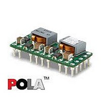
PMN5118UP Ericsson Power Modules, PMN5118UP Datasheet - Page 31

PMN5118UP
Manufacturer Part Number
PMN5118UP
Description
DC/DC Converters & Regulators 0.7-3.6V 30A Non-Iso Input 4.5-5.5V 108W
Manufacturer
Ericsson Power Modules
Series
PMNr
Datasheet
1.PMN5118USR.pdf
(37 pages)
Specifications of PMN5118UP
Output Power
108 W
Input Voltage Range
4.5 V to 5.5 V
Number Of Outputs
1
Output Voltage (channel 1)
0.7 V to 3.6 V
Output Current (channel 1)
30 A
Output Type
POLA Non-Isolated Regulator
Product
Non-Isolated / POL
Lead Free Status / RoHS Status
Lead free / RoHS Compliant
Available stocks
Company
Part Number
Manufacturer
Quantity
Price
Part Number:
PMN5118UP
Manufacturer:
ERICSSON/爱立信
Quantity:
20 000
Thermal Consideration continued
Definition of reference temperature (T
The reference temperature is used to monitor the temperature
limits of the product. Temperatures above maximum T
not allowed and may cause degradation or permanent
damage to the product. T
temperature range for normal operating conditions.
T
margins, proper operation and high reliability of the module.
Ambient Temperature Calculation
By using the thermal resistance the maximum allowed
ambient temperature can be calculated.
1. The power loss is calculated by using the formula
((1/η) - 1) × output power = power losses (Pd).
η = efficiency of regulator. E.g 89.5 % = 0.895
2. Find the thermal resistance (Rth) in the Thermal Resistance
graph found in the Output section for each model.
Calculate the temperature increase (∆T).
3. Max allowed ambient temperature is:
Max Tref - ∆T.
E.g PMN 5118U P at 0m/s:
1. ((
2. 5.54 W × 15.2°C/W = 84.2°C
3. 130 °C — 84.2°C = max ambient temperature is 45.8°C
The actual temperature will be dependent on several factors
such as the PCB size, number of layers and direction of
airflow.
E
∆T = Rth x Pd
Prepared (also subject responsible if other)
EYIPYAN
Approved
SEC/D (Julia You)
PMN 5000 series
POL regulator, Input 4.5-5.5 V, Output up to 30 A/108 W
ref
is defined by the design and used to guarantee safety
0.947
1
) - 1) × 99 W = 5.54 W
ref
is also used to define the
ref
)
Checked
EQUENXU
ref
are
Connections
Ericsson Internal
PRODUCT SPECIFICATION
No.
3/1301-BMR656 5118 Uen
Date
2007-7-9
Pin Designation Function
1
2
3
4
5
6
Inhibit/
UVLO Adjust
V
GND
GND
V
V
I
o
I
Technical Specification
EN/LZT 146 386 R1A
© Ericsson Power Modules AB
Rev
B
The Inhibit pin is an open-collector/drain,
negative logic input that is referenced to
GND. Applying a low level ground signal
to this input disables the module’s output
voltage. If the Inhibit pin is left open-
circuit, the module produces an output
whenever a valid input source is applied.
This input is not compatible with TTL
logic devices and should not be tied V
other voltage.
This pin is also used for input
undervoltage lockout (UVLO)
programming. Connecting a resistor from
this pin to GND (Pin 3) allows the ON
threshold of the UVLO to be adjusted
higher than the default value.
The positive input voltage power node to
the module, which is referenced to
common GND.
This is the common ground connection
for the V
also the 0 V
inputs.
This is the common ground connection
for the V
also the 0 V
inputs.
The regulated positive power output with
respect to the GND.
The positive input voltage power node to
the module, which is referenced to
common GND.
I
I
and V
and V
Reference
dc
dc
reference for the control
reference for the control
o
o
power connections. It is
power connections. It is
July 2007
6 (8)
31
I
or


