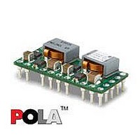
PMN5118UP Ericsson Power Modules, PMN5118UP Datasheet - Page 28

PMN5118UP
Manufacturer Part Number
PMN5118UP
Description
DC/DC Converters & Regulators 0.7-3.6V 30A Non-Iso Input 4.5-5.5V 108W
Manufacturer
Ericsson Power Modules
Series
PMNr
Datasheet
1.PMN5118USR.pdf
(37 pages)
Specifications of PMN5118UP
Output Power
108 W
Input Voltage Range
4.5 V to 5.5 V
Number Of Outputs
1
Output Voltage (channel 1)
0.7 V to 3.6 V
Output Current (channel 1)
30 A
Output Type
POLA Non-Isolated Regulator
Product
Non-Isolated / POL
Lead Free Status / RoHS Status
Lead free / RoHS Compliant
Available stocks
Company
Part Number
Manufacturer
Quantity
Price
Part Number:
PMN5118UP
Manufacturer:
ERICSSON/爱立信
Quantity:
20 000
E
If the remote sense is not needed +Sense should be
connected to +Out and -Sense should be connected to -Out.
Over Temperature Protection (OTP)
The regulators are protected from thermal overload by an
internal over temperature shutdown circuit.
When T
exceeds the OTP threshold, the regulator will shut down. The
DC/DC regulator will make continuous attempts to start up
(non-latching mode) and resume normal operation
automatically when the temperature has dropped >10°C
below the temperature threshold.
Over Current Protection (OCP)
The regulators include current limiting circuitry for protection
at continuous overload.
The output voltage will decrease towards zero for output
currents in excess of max output current (max I
regulator will resume normal operation after removal of the
overload. The load distribution should be designed for the
maximum output short circuit current specified.
Soft-start Power Up
From the moment a valid input voltage is applied, the soft-
start control introduces a short time-delay (typically 5-10 ms)
before allowing the output voltage to rise.
The initial rise in input current when the input voltage first
starts to rise is the charge current drawn by the input
capacitors. Power-up is complete within 15 ms.
Auto Track™ Function
Auto Track
required to make the output voltage from each module
power up and power down in sequence. The sequencing of
two or more supply voltages during power up is a common
requirement for complex mixed-signal applications, that use
dual-voltage VLSI ICs such as DSPs, micro-processors and
ASICs.
Adjustable Undervoltage Lockout
The regulators incorporate an input undervoltage lockout
(UVLO). The UVLO feature prevents the operation of the
module until there is a sufficient input voltage to produce a
valid output voltage. This enables the module to provide a
clean, monotonic powerup for the load circuit and also limit
the magnitude of current drawn from regulator’s input source
during the power-up sequence.
The UVLO characteristic is defined by the ON threshold (V
voltage. Below the ON threshold, the Inhibit control is
overridden, and the moudule does not produce an output.
The hysterisis voltage, which is the difference oscillations,
which can occur if the input voltage drops slightly when the
modules begins to draw current from the input source.
The UVLO feature of the PMN 5118U P module allows for
Prepared (also subject responsible if other)
EYIPYAN
Approved
SEC/D (Julia You)
PMN 5000 series
POL regulator, Input 4.5-5.5 V, Output up to 30 A/108 W
ref
as defined in thermal consideration section
TM
was designed to simplify the amount of circuitry
O
). The
Checked
EQUENXU
THD
)
Ericsson Internal
PRODUCT SPECIFICATION
No.
3/1301-BMR656 5118 Uen
Date
2007-7-9
limited adjustment of the ON threshold voltage. The
adjustment is made via the Inhibit/UVLO Prog control pin (Pin
1) using a single resistor (see figure below). When pin 1 is left
open, the ON threshold voltage is intermally set to its default
value. The ON threshold has a nominal voltage of 4.25 V and
a hysterisis of 150 mV.
The below equation determines the value of R
to adjust V
it may only be adjusted to a higher value.
The above table lists the standard resistor values for R
different values of the ON threshold (V
The figure of UVLO Program Resistor Placement is as follow.
Turbo Trans
Turbo Trans
regulator with added external capacitance using a single
external resistor. The benefits of this technology include:
reduced output capacitance, minimized output voltage
deviation following a load transient, and enhanced stability
when using ultra-low ESR output capacitors. The amout of
output capacitance required to meet a target output voltage
deviation, is reduded with Turbo Trans
for a given amout of output capacitance, with Turbo Trans
engaged, the amplitude of the voltage deviation following a
load transient is reduced. Applications requiring tight
transient voltage tolerances and minimized capacitor footprint
area benefit from this technology.
between the +Sense pin (pin 10) and the Turbo Trans
(pin 13), The value of the resistor directly corresponds to the
amount of output capacitance required. For the PMN 5118U
P, the minimum required capacitance is 470 µF. When using
Turbo Trans
R
Utilizing Turbo Trans
UVLO
=
101
THD
V
TM
TM
TM
THD
, capacitors with a capacitance×ESR product
to a new value. The default value is 4.25 V and
Technology
optimizes the transient response of the
−
V
−
Technical Specification
EN/LZT 146 386 R1A
© Ericsson Power Modules AB
THD
Rev
B
1
TM
requires connecting a resistor, R
(KΩ)
Reference
THD
TM
July 2007
activated. Likewise,
) voltage.
UVLO
required
TM
UVLO
pin
3 (8)
TT
28
TM
,
for


