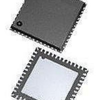
ASD5010L500INT Arctic Silicon Devices, ASD5010L500INT Datasheet - Page 21

ASD5010L500INT
Manufacturer Part Number
ASD5010L500INT
Description
ADC (A/D Converters) A-D Conv, Dig Gain Dual 8 bit 500MSPS
Manufacturer
Arctic Silicon Devices
Datasheet
1.ASD5010L500INT.pdf
(35 pages)
Specifications of ASD5010L500INT
Number Of Converters
2
Number Of Adc Inputs
4
Conversion Rate
500 MSPs
Resolution
8 bit
Snr
49.5 dB
Voltage Reference
1 V
Supply Voltage (max)
2 V
Supply Voltage (min)
1.7 V
Maximum Power Dissipation
295 mW
Maximum Operating Temperature
+ 85 C
Mounting Style
SMD/SMT
Package / Case
QFN-48
Input Voltage
1.8 V
Minimum Operating Temperature
- 40 C
Lead Free Status / RoHS Status
Lead free / RoHS Compliant
Preliminary Product Specification
Start-up and Clock Jitter Control
To optimize start up time, a register is provided where the start-up time in number of clock cycles can be set. Some
internal circuitry have start up times that are clock frequency independent. Default counter values are set to
accommodate these start up times at the maximum clock frequency (sampling rate). This will lead to increased start up
times at low clock frequencies. Setting the value of this register to the nearest higher clock frequency will reduce the
count values of the internal counters, to better fit the actual start up time, such that the start up time will be reduced. The
start up times from power down and sleep modes are changed by this register setting. If the clock divider is used (set to
other than 1), the input clock frequency must be divided by the divider factor to find the correct clock frequency range
(see table 7).
jitter_ctrl<7:0> allows the user to set a trade-off between power consumption and clock jitter. If all bits in the register is
set low, the clock signal is stopped. The clock jitter depends on the number of bits set to '1' in the jitter_ctrl<7:0> register.
Which bits are set high does not affect the result.
ASD5010
startup_ctrl<2:0>
jitter_ctrl<7:0>
ctrl<2:0>
ctrl<2:0>
startup_
startup_
other
other
100
000
001
010
100
000
001
010
011
011
Name
Clock frequency
Clock frequency
Do not use
640 - 1000
Do not use
160 - 250
100 - 160
400 - 640
260 - 400
160 - 260
120 - 160
65 - 100
[MSPS]
[MSPS]
40 - 65
30 - 40
Controls start-up time.
Clock jitter adjustment.
range
range
Single channel
Quad channel
Description
[clock cycles]
[clock cycles]
Startup delay
Startup delay
12288
3072
1984
1280
7936
5120
3360
2080
840
520
-
-
Table 12: Start-up time control settings
12.3 – 19.2
12.3 – 19.2
delay [µs]
delay [µs]
12.4 - 19.8
12.8 - 19.7
12.4 - 19.8
12.8 - 19.7
12.9 - 21
13 - 17.3
12.9 - 21
13 - 17.3
Startup
Startup
rev 2.0, 2010.11.08
-
-
160 fsrms
Default
Page 21 of 35
'000'
ctrl<2:0>
startup_
D15 D14D13D12D11D10 D9 D8 D7 D6 D5 D4 D3 D2 D1 D0
other
100
000
001
010
011
Clock frequency
Do not use
130 – 200
320 - 500
200 - 320
80 - 130
[MSPS]
60 – 80
range
Dual channel
X X X X X X X X
[clock cycles]
Startup delay
6144
3968
2560
1680
1040
-
X X X
Confidential
12.3 – 19.2
12.4 - 19.8
12.8 - 19.7
delay [µs]
12.9 - 21
13 - 17.3
Startup
Address
-
0x56
0x30
Hex


