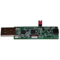
DLP-FLASH2 DLP Design Inc, DLP-FLASH2 Datasheet - Page 2

DLP-FLASH2
Manufacturer Part Number
DLP-FLASH2
Description
Programmers & Debuggers DEVICE PROG/ INCIRCT DEBUGR W/ C COMPILER
Manufacturer
DLP Design Inc
Datasheet
1.DLP-FLASH2.pdf
(5 pages)
Specifications of DLP-FLASH2
Positions/sockets
1
For Use With/related Products
PIC16F, PIC18F
The DLP-FLASH2 programmer is compatible with the family of CCS C compilers. The DLP-FLASH2
is directly supported by the IDE programming environment as well as by the ICD programming
software available from CCS.
3.0 POWER CONSIDERATIONS
The DLP-FLASH2 programmer board has the ability to supply 5-volt power—via the programming
header—to the target microcontroller for programming and debug. The circuitry that is connected to
Pin 5 of the DLP-FLASH2 programmer must not draw more than 300mA. If the target electronics
draw more than 300mA on the 5-volt line or the target operates at a voltage other than 5 volts, then
they must be externally powered and electrically isolated from the DLP-FLASH2 by removing the
TPWR jumper.
NOTE: If programming a microcontroller that is installed in target electronics, it will most likely
be necessary to apply power to the target’s circuitry before programming. The DLP-FLASH2
programmer can supply a minimal amount of 5-volt power for either a circuit that requires very
little power or for just a microcontroller. As a rule of thumb, if the microcontroller to be
programmed is connected to target electronics, always apply power to the microcontroller and
remove the TPWR jumper before connecting to the DLP-FLASH2.
4.0 QUICK-START GUIDE
This guide requires the use of a Windows 2000/XP PC that is equipped with a USB port. If the DLP-
FLASH board is connected to your PC, unplug it at this time.
1. Download the CDM drivers from this page: www.dlpdesign.com/flash2/. Unzip the drivers into a
2. Connect the DLP-FLASH programmer board to the PC. A USB extension cable of 10 feet or less
3. This action initiates the loading of the USB drivers. When prompted, select the folder where the
4. At this point, the DLP-FLASH2 is ready for use. Run the CCS IDE software or the ICD control
For additional information on how to use the CCS debugger, visit the CCS website:
http://www.ccsinfo.com/content.php?page=debugger
Rev. 1.1 (September 2007)
folder on the hard drive. (Be sure to “Extract” the files from the archive so as to maintain the folder
structure.)
in length can be used to allow more freedom of movement with the DLP-FLASH2.
device drivers were stored in Step 1. Windows will then complete the installation of the device
drivers for the DLP-FLASH2 board. The next time the DLP-FLASH2 module is attached, the host
PC will immediately load the correct drivers without any prompting. Reboot the PC if prompted to
do so.
software.
2
© DLP Design, Inc.


