OM11042,598 NXP Semiconductors, OM11042,598 Datasheet - Page 32
OM11042,598
Manufacturer Part Number
OM11042,598
Description
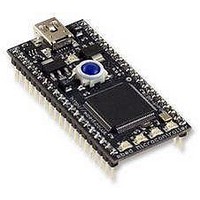
Microcontroller Modules & Accessories mbed LPC2368 Demo Board
Manufacturer
NXP Semiconductors
Datasheet
1.OM11042598.pdf
(59 pages)
Specifications of OM11042,598
Product
Microcontroller Modules
Data Bus Width
32 bit
Core Processor
LPC2368
Clock Speed
60 MHz
Interface Type
Ethernet, CAN, I2C, SPI, UART
Operating Supply Voltage
3 V to 3.6 V
Lead Free Status / RoHS Status
Lead free / RoHS Compliant


NXP Semiconductors
LPC2364_65_66_67_68_6
Product data sheet
7.24.4.3 Power-down mode
7.24.4.4 Deep power-down mode
7.24.4.5 Power domains
On the wake-up of Sleep mode, if the IRC was used before entering Sleep mode, the
code execution and peripherals activities will resume after 4 cycles expire. If the main
external oscillator was used, the code execution will resume when 4096 cycles expire.
The customers need to reconfigure the PLL and clock dividers accordingly.
Power-down mode does everything that Sleep mode does, but also turns off the IRC
oscillator and the flash memory. This saves more power, but requires waiting for
resumption of flash operation before execution of code or data access in the flash memory
can be accomplished.
On the wake-up of Power-down mode, if the IRC was used before entering Power-down
mode, it will take IRC 60 μs to start-up. After this 4 IRC cycles will expire before the code
execution can then be resumed if the code was running from SRAM. In the meantime, the
flash wake-up timer then counts 4 MHz IRC clock cycles to make the 100 μs flash start-up
time. When it times out, access to the flash will be allowed. The customers need to
reconfigure the PLL and clock dividers accordingly.
Deep power-down mode is similar to the Power-down mode, but now the on-chip
regulator that supplies power to the internal logic is also shut off. This produces the lowest
possible power consumption without removing power from the entire chip. Since the Deep
power-down mode shuts down the on-chip logic power supply, there is no register or
memory retention, and resumption of operation involves the same activities as a full chip
reset.
If power is supplied to the LPC2364/65/66/67/68 during Deep power-down mode,
wake-up can be caused by the RTC Alarm interrupt or by external Reset.
While in Deep power-down mode, external device power may be removed. In this case,
the LPC2364/65/66/67/68 will start up when external power is restored.
Essential data may be retained through Deep power-down mode (or through complete
powering off of the chip) by storing data in the Battery RAM, as long as the external power
to the VBAT pin is maintained.
The LPC2364/65/66/67/68 provides two independent power domains that allow the bulk
of the device to have power removed while maintaining operation of the RTC and the
battery RAM.
On the LPC2364/65/66/67/68, I/O pads are powered by the 3.3 V (V
the V
power to the CPU and most of the peripherals.
Depending on the LPC2364/65/66/67/68 application, a design can use two power options
to manage power consumption.
DD(DCDC)(3V3)
pin powers the on-chip DC-to-DC converter which in turn provides
Rev. 06 — 1 February 2010
LPC2364/65/66/67/68
Single-chip 16-bit/32-bit microcontrollers
DD(3V3)
© NXP B.V. 2010. All rights reserved.
) pins, while
32 of 59
Related parts for OM11042,598
Image
Part Number
Description
Manufacturer
Datasheet
Request
R

Part Number:
Description:
DEVELOPMENT BOARD FOR LPC2368
Manufacturer:
NXP Semiconductors
Datasheet:

Part Number:
Description:
NXP Semiconductors designed the LPC2420/2460 microcontroller around a 16-bit/32-bitARM7TDMI-S CPU core with real-time debug interfaces that include both JTAG andembedded trace
Manufacturer:
NXP Semiconductors
Datasheet:

Part Number:
Description:
NXP Semiconductors designed the LPC2458 microcontroller around a 16-bit/32-bitARM7TDMI-S CPU core with real-time debug interfaces that include both JTAG andembedded trace
Manufacturer:
NXP Semiconductors
Datasheet:
Part Number:
Description:
NXP Semiconductors designed the LPC2468 microcontroller around a 16-bit/32-bitARM7TDMI-S CPU core with real-time debug interfaces that include both JTAG andembedded trace
Manufacturer:
NXP Semiconductors
Datasheet:
Part Number:
Description:
NXP Semiconductors designed the LPC2470 microcontroller, powered by theARM7TDMI-S core, to be a highly integrated microcontroller for a wide range ofapplications that require advanced communications and high quality graphic displays
Manufacturer:
NXP Semiconductors
Datasheet:
Part Number:
Description:
NXP Semiconductors designed the LPC2478 microcontroller, powered by theARM7TDMI-S core, to be a highly integrated microcontroller for a wide range ofapplications that require advanced communications and high quality graphic displays
Manufacturer:
NXP Semiconductors
Datasheet:
Part Number:
Description:
The Philips Semiconductors XA (eXtended Architecture) family of 16-bit single-chip microcontrollers is powerful enough to easily handle the requirements of high performance embedded applications, yet inexpensive enough to compete in the market for hi
Manufacturer:
NXP Semiconductors
Datasheet:
Part Number:
Description:
The XA-S3 device is a member of Philips Semiconductors? XA(eXtended Architecture) family of high performance 16-bitsingle-chip microcontrollers
Manufacturer:
NXP Semiconductors
Datasheet:

Part Number:
Description:
The NXP BlueStreak LH75401/LH75411 family consists of two low-cost 16/32-bit System-on-Chip (SoC) devices
Manufacturer:
NXP Semiconductors
Datasheet:
Part Number:
Description:
The NXP LPC3130/3131 combine an 180 MHz ARM926EJ-S CPU core, high-speed USB2
Manufacturer:
NXP Semiconductors
Datasheet:
Part Number:
Description:
The NXP LPC3141 combine a 270 MHz ARM926EJ-S CPU core, High-speed USB 2
Manufacturer:
NXP Semiconductors
Part Number:
Description:
The NXP LPC3143 combine a 270 MHz ARM926EJ-S CPU core, High-speed USB 2
Manufacturer:
NXP Semiconductors

Part Number:
Description:
The NXP LPC3152 combines an 180 MHz ARM926EJ-S CPU core, High-speed USB 2
Manufacturer:
NXP Semiconductors
Part Number:
Description:
The NXP LPC3154 combines an 180 MHz ARM926EJ-S CPU core, High-speed USB 2
Manufacturer:
NXP Semiconductors