OM11042,598 NXP Semiconductors, OM11042,598 Datasheet - Page 27
OM11042,598
Manufacturer Part Number
OM11042,598
Description
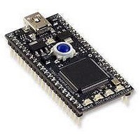
Microcontroller Modules & Accessories mbed LPC2368 Demo Board
Manufacturer
NXP Semiconductors
Datasheet
1.OM11042598.pdf
(59 pages)
Specifications of OM11042,598
Product
Microcontroller Modules
Data Bus Width
32 bit
Core Processor
LPC2368
Clock Speed
60 MHz
Interface Type
Ethernet, CAN, I2C, SPI, UART
Operating Supply Voltage
3 V to 3.6 V
Lead Free Status / RoHS Status
Lead free / RoHS Compliant


NXP Semiconductors
LPC2364_65_66_67_68_6
Product data sheet
7.20.1 Features
7.20 General purpose 32-bit timers/external event counters
7.21 Pulse width modulator
The LPC2364/65/66/67/68 include four 32-bit Timer/Counters. The Timer/Counter is
designed to count cycles of the system derived clock or an externally-supplied clock. It
can optionally generate interrupts or perform other actions at specified timer values,
based on four match registers. The Timer/Counter also includes two capture inputs to trap
the timer value when an input signal transitions, optionally generating an interrupt.
The PWM is based on the standard Timer block and inherits all of its features, although
only the PWM function is pinned out on the LPC2364/65/66/67/68. The Timer is designed
to count cycles of the system derived clock and optionally switch pins, generate interrupts
or perform other actions when specified timer values occur, based on seven match
registers. The PWM function is in addition to these features, and is based on match
register events.
The ability to separately control rising and falling edge locations allows the PWM to be
used for more applications. For instance, multi-phase motor control typically requires
three non-overlapping PWM outputs with individual control of all three pulse widths and
positions.
Two match registers can be used to provide a single edge controlled PWM output. One
match register (PWMMR0) controls the PWM cycle rate, by resetting the count upon
match. The other match register controls the PWM edge position. Additional single edge
controlled PWM outputs require only one match register each, since the repetition rate is
the same for all PWM outputs. Multiple single edge controlled PWM outputs will all have a
rising edge at the beginning of each PWM cycle, when an PWMMR0 match occurs.
•
•
•
•
•
A 32-bit Timer/Counter with a programmable 32-bit prescaler.
Counter or Timer operation.
Two 32-bit capture channels per timer, that can take a snapshot of the timer value
when an input signal transitions. A capture event may also generate an interrupt.
Four 32-bit match registers that allow:
– Continuous operation with optional interrupt generation on match.
– Stop timer on match with optional interrupt generation.
– Reset timer on match with optional interrupt generation.
Up to four external outputs corresponding to match registers, with the following
capabilities:
– Set LOW on match.
– Set HIGH on match.
– Toggle on match.
– Do nothing on match.
Rev. 06 — 1 February 2010
LPC2364/65/66/67/68
Single-chip 16-bit/32-bit microcontrollers
© NXP B.V. 2010. All rights reserved.
27 of 59
Related parts for OM11042,598
Image
Part Number
Description
Manufacturer
Datasheet
Request
R

Part Number:
Description:
DEVELOPMENT BOARD FOR LPC2368
Manufacturer:
NXP Semiconductors
Datasheet:

Part Number:
Description:
NXP Semiconductors designed the LPC2420/2460 microcontroller around a 16-bit/32-bitARM7TDMI-S CPU core with real-time debug interfaces that include both JTAG andembedded trace
Manufacturer:
NXP Semiconductors
Datasheet:

Part Number:
Description:
NXP Semiconductors designed the LPC2458 microcontroller around a 16-bit/32-bitARM7TDMI-S CPU core with real-time debug interfaces that include both JTAG andembedded trace
Manufacturer:
NXP Semiconductors
Datasheet:
Part Number:
Description:
NXP Semiconductors designed the LPC2468 microcontroller around a 16-bit/32-bitARM7TDMI-S CPU core with real-time debug interfaces that include both JTAG andembedded trace
Manufacturer:
NXP Semiconductors
Datasheet:
Part Number:
Description:
NXP Semiconductors designed the LPC2470 microcontroller, powered by theARM7TDMI-S core, to be a highly integrated microcontroller for a wide range ofapplications that require advanced communications and high quality graphic displays
Manufacturer:
NXP Semiconductors
Datasheet:
Part Number:
Description:
NXP Semiconductors designed the LPC2478 microcontroller, powered by theARM7TDMI-S core, to be a highly integrated microcontroller for a wide range ofapplications that require advanced communications and high quality graphic displays
Manufacturer:
NXP Semiconductors
Datasheet:
Part Number:
Description:
The Philips Semiconductors XA (eXtended Architecture) family of 16-bit single-chip microcontrollers is powerful enough to easily handle the requirements of high performance embedded applications, yet inexpensive enough to compete in the market for hi
Manufacturer:
NXP Semiconductors
Datasheet:
Part Number:
Description:
The XA-S3 device is a member of Philips Semiconductors? XA(eXtended Architecture) family of high performance 16-bitsingle-chip microcontrollers
Manufacturer:
NXP Semiconductors
Datasheet:

Part Number:
Description:
The NXP BlueStreak LH75401/LH75411 family consists of two low-cost 16/32-bit System-on-Chip (SoC) devices
Manufacturer:
NXP Semiconductors
Datasheet:
Part Number:
Description:
The NXP LPC3130/3131 combine an 180 MHz ARM926EJ-S CPU core, high-speed USB2
Manufacturer:
NXP Semiconductors
Datasheet:
Part Number:
Description:
The NXP LPC3141 combine a 270 MHz ARM926EJ-S CPU core, High-speed USB 2
Manufacturer:
NXP Semiconductors
Part Number:
Description:
The NXP LPC3143 combine a 270 MHz ARM926EJ-S CPU core, High-speed USB 2
Manufacturer:
NXP Semiconductors

Part Number:
Description:
The NXP LPC3152 combines an 180 MHz ARM926EJ-S CPU core, High-speed USB 2
Manufacturer:
NXP Semiconductors
Part Number:
Description:
The NXP LPC3154 combines an 180 MHz ARM926EJ-S CPU core, High-speed USB 2
Manufacturer:
NXP Semiconductors