LPC1766-STK Olimex Ltd., LPC1766-STK Datasheet - Page 12
LPC1766-STK
Manufacturer Part Number
LPC1766-STK
Description
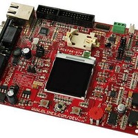
MCU, MPU & DSP Development Tools DEV BRD FOR LPC1766 256KB FLASH 64KB RAM
Manufacturer
Olimex Ltd.
Datasheet
1.LPC1766-STK.pdf
(24 pages)
Specifications of LPC1766-STK
Processor To Be Evaluated
LPC1766
Data Bus Width
32 bit
Interface Type
RS-232, Ethernet, USB, CAN, I2C, SPI, UART
Dimensions
134.6 mm x 101.6 mm
Operating Supply Voltage
3.3 V
Lead Free Status / RoHS Status
Lead free / RoHS Compliant
Available stocks
Company
Part Number
Manufacturer
Quantity
Price
Company:

Part Number:
LPC1766-STK
Manufacturer:
Olimex Ltd.
Quantity:
135


USB_D+
PWR_SEL
INPUT/OUTPUT:
enables USB HOST and when 5-6 are shorted – enables USB OTG.
Default state is 1-2.
– the board is supplied from JTAG and when 5-6 are shorted – the board is supplied from
USB_DEV.
Default state is 1-2.
This jumper, when1-2 are shorted – enables USB DEVICE, when 3-4 are shorted–
When 1-2 are shorted – the board is supplied from PWR_JACK, when 3-4 are shorted
LED1 (red) connected to LPC1766 pin 39 (P1[25]/MC1A/MAT1[1]).
LED2 (red) connected to LPC1766 pin 81 (P0[4]/I2SRX_CLK/RD2/CAP2[0]) via
jumper ACC_IRQ/LED2, when this jumper is in position LED2.
SD/MMC LED (red) connected to SD/MMC pin 4 (VDD).
Power-on LED (red) with name PWR – this LED shows that +3.3V is applied to the
board.
USB_UP_LED with name USB_LINK (yellow) connected to LPC1766 pin 32
(P1[18]/USB_UP_LED/PWM1[1]/CAP1[0]).
USBD_CONNECT LED with name USBC(green) connected to LPC1766 pin 64
(P2[9]/USB_CONNECT/RXD2) through T3 and R29.
User button with name BUT1 connected to LPC1766 pin 9
(P0[23]/AD0[0]/I2SRX_CLK/CAP3[0]).
User button with name BUT2 connected to LPC1766 pin 50
(P2[13]/#EINT3/I2STX_SDA).
User button with name WAKE-UP connected to LPC1766 pin 51
(P2[12]/#EINT2/I2STX_WS).
User button with name RESET connected to LPC1766 pin 17 (#RESET).
Joystick button with name J1 this is 4 directions plus center button, in the
schematic the joystick four directions switches are connected through 33k resistors
to LPC1766 pins - 65 (P2[8]/TD2/TXD2) – RIGHT, 66 (P2[7]/RD2/RTS1) – LEFT, 74
(P2[1]/PWM1[2]/RXD1) – DOWN, 75 (P2[0]/PWM1[1]/TXD1) – UP, the center
button is connected to pin 80 (P0[5]/I2SRX_WS/TD2/CAP2[1]).
Trimpot with name AN_TRIM connected to LPC1766 pin 20
(P1[31]/SCK1/AD0[5]).
TFT LCD - 128x128 12 bit color with backlight.
Page 12
Related parts for LPC1766-STK
Image
Part Number
Description
Manufacturer
Datasheet
Request
R

Part Number:
Description:
MCU, MPU & DSP Development Tools ETHERNET CONTROLLER HEADER BRD 50x40mm
Manufacturer:
Olimex Ltd.
Datasheet:

Part Number:
Description:
MCU, MPU & DSP Development Tools DEV PROTOTYPE BRD FOR TMS470A256
Manufacturer:
Olimex Ltd.
Datasheet:

Part Number:
Description:
MCU, MPU & DSP Development Tools ETHERNET CONTROLLER HEADER BRD 53x29mm
Manufacturer:
Olimex Ltd.
Datasheet:

Part Number:
Description:
MCU, MPU & DSP Development Tools MP3 PLYR MOD WVS1002 W/VS1002
Manufacturer:
Olimex Ltd.
Datasheet:

Part Number:
Description:
MCU, MPU & DSP Development Tools PoE INJECTOR FOR PIC-MICRO-WEB
Manufacturer:
Olimex Ltd.

Part Number:
Description:
Development Boards & Kits - ARM OLINUXINO MICRO SBC ALLWINNER A10S CTXA8
Manufacturer:
Olimex Ltd.
Part Number:
Description:
Other Development Tools EKG / EMG SHIELD FOR DUINOMITE
Manufacturer:
Olimex Ltd.

Part Number:
Description:
MCU, MPU & DSP Development Tools DEV BRD FOR LPC2378 512KB FLASH 16KB RAM
Manufacturer:
Olimex Ltd.

Part Number:
Description:
MCU, MPU & DSP Development Tools HDR BRD FOR LPC2294 1MB SRAM 4MB FLASH
Manufacturer:
Olimex Ltd.

Part Number:
Description:
MCU, MPU & DSP Development Tools DEV BRD FOR LPC2919 768KB FLASH 56KBSRAM
Manufacturer:
Olimex Ltd.
Datasheet:

Part Number:
Description:
Microcontroller & Microprocessor Development Tools HDR BRD FOR LPC3131
Manufacturer:
Olimex Ltd.
Datasheet:

Part Number:
Description:
Microcontroller & Microprocessor Development Tools TCP-IP DEV BRD PIC32MX460F512
Manufacturer:
Olimex Ltd.
Datasheet:

Part Number:
Description:
Microcontroller & Microprocessor Development Tools PROTOTYPE BOARD TMS320F28027
Manufacturer:
Olimex Ltd.
Datasheet:

Part Number:
Description:
Microcontroller & Microprocessor Development Tools MP3 PLYR MOD WITH VS1002
Manufacturer:
Olimex Ltd.
Datasheet:
Part Number:
Description:
Microcontroller & Microprocessor Development Tools MP3 PLYR MOD BAT WITH VS1002
Manufacturer:
Olimex Ltd.
Datasheet: