LPC-H3131 Olimex Ltd., LPC-H3131 Datasheet
LPC-H3131
Specifications of LPC-H3131


Related parts for LPC-H3131


LPC-H3131 Summary of contents
Page 1
... LPC-H3131 development board All boards produced by Olimex are ROHS compliant Copyright(c) 2010, OLIMEX Ltd, All rights reserved Users Manual Rev. Initial, May 2010 Page1 ...
Page 2
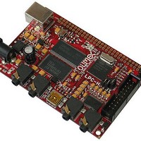
... INTRODUCTION LPC-H3131 board includes powerful LPC3131 180 MHz ARM microcontroller, with 4 Gb NAND FLASH, 256 Mb SDRAM, which gives user opportunity to run Embeded Linux operation systems. In addition there is audio codec, which gives chance to be made audio signal processing; USB_OTG; USB to UART; mini SD/MMC card connector ...
Page 3
... ELECTROSTATIC WARNING The LPC-H3131 board is shipped in protective anti-static packaging. The board must not be subject to high electrostatic potentials. General practice for working with static sensitive devices should be applied when working with this board. BOARD USE REQUIREMENTS Cables: The cable you will need depends on the programmer/debugger you use. If you use ARM-USB-TINY or ARM-USB-TINY-H, you will need USB A-B cable and if you use ARM-USB-OCD, you will need RS232 and USB A-B cable ...
Page 4
Dynamic clock gating and scaling – Multiple power domains – Selectable boot-up: SPI flash, NAND flash, SD/MMC cards, UART, or – USB DMA controller – Four 32-bit timers – Watchdog timer – PWM module – Random Number Generator (RNG) – ...
Page 5
BLOCK DIAGRAM Page5 ...
Page 6
MEMORY MAP Page6 ...
Page 7
... LED2 LED1 GYX-SD-TC0805S GC(GREEN) GYX-SD-TC0805SYC(YELLOW) R39 R40 560R 560R C48 C47 C46 C38 C36 100nF 100nF 100nF 100nF 100nF LPC-H3131 Rev. Initial L1 COPYRIGHT(C) 2010, OLIMEX Ltd. 1.25V FB0 http://www.olimex.com/dev 1 0u F/6 .3V L2 3.3V FB0 R70 10k L3 3.3V R71 10k +5V 3.3V 3 ...
Page 8
BOARD LAYOUT Page8 ...
Page 9
... The board power consumption is about 110 mA. RESET CIRCUIT LPC-H3131 reset circuit includes JTAG connector pin 15, U2 (NAND Flash) pin 19 (#WP), U7 (SPI-Flash) pin 3 (/RESET/) and pin 5 (/WP/), D5 (1N4148), C80 (100nF), R64 (100 Ohm), R32 (10k), R47 (330 Ohm), LPC3131 pin H14 (RSTIN_N) and Reset button ...
Page 10
... Default state is closed. INPUT/OUTPUT User led (yellow) with name LED1 – connected to LPC3131 pin K12 (GPIO17). User led (green) with name LED2 – connected to LPC3131 pin K14 (GPIO18). Power-on led (red) with name PWR - this LED shows that +3.3V is applied to the board. Reset button with name RESET – ...
Page 11
CONNECTOR DESCRIPTIONS JTAG Pin # Signal Name Pin # Signal Name 3.3V 2 3.3V TRST_N 4 GND TDI 6 GND TMS 8 GND TCK 10 GND RTCK 12 GND TDO ...
Page 12
EXT Pin# Signal Name 1 3.3V 2 GND 3 RST 4 EXT1-4 5 EXT1-5 6 EXT1-6 7 EXT1-7 8 EXT1-8 9 EXT1-9 10 EXT1-10 11 EXT1-11 12 EXT1-12 13 EXT1-13 14 EXT1-14 15 EXT1-15 16 EXT1-16 17 EXT1-17 18 EXT1-18 ...
Page 13
USB_TO_UART Pin # Signal Name 1 USB_PWR 2 USBDM 3 USBDP 4 GND USB_OTG Pin # Signal Name 1 +5V_OTG_PWR 2 USB_OTG_D- 3 USB_OTG_D+ 4 USB_OTG_ID 5 GNDA PWR_JACK Pin # Signal Name 1 Power Input 2 GND Page13 ...
Page 14
MICROPHONE Pin # Signal Name 1 AGND MIC HEADPHONE Pin # 1 VOUTLHP (left channel) 2 VREF(HP) (common) 3 VOUTRHP (right channel) LINE_IN Pin # 1 VINL (left channel) 2 AGND 3 VINR (right channel) Signal Name ...
Page 15
LINE_OUT Pin # 1 VOUTL (left channel) 2 AGND 3 VOUTR (right channel) SD/MMC Pin # Signal Name 1 MCI_DAT_2 2 MCI_DAT_3 3 MCI_CMD 4 VDD (power supply) 5 MCI_CLK 6 GND 7 MCI_DAT_0 8 MCI_DAT_1 9 Not connected 10 ...
Page 16
... Supports maskable interrupts. – Supports DMA transfers. – C-bus master/slave interface The LPC3131 contains two I This module has the following features C-bus interface – open-drain pins. This interface supports functions described in the I specification for speeds up to 400 kHz. This includes multi-master operation and allows powering off this device in a working system while leaving the I bus functional ...
Page 17
MECHANICAL DIMENSIONS Page17 ...
Page 18
AVAILABLE DEMO SOFTWARE Page18 ...
Page 19
... ORDER CODE LPC-H3131 How to order? You can order to us directly or by any of our distributors. Check our web Revision history: REV. Initial – assembled and tested www.olimex.com/dev for more info. - create May 2010 Page19 ...
Page 20
... This document is intended only to assist the reader in the use of the product. OLIMEX Ltd. shall not be liable for any loss or damage arising from the use of any information in this document or any error or omission in such information or any incorrect use of the product ...