OM6271 NXP Semiconductors, OM6271 Datasheet - Page 15
OM6271
Manufacturer Part Number
OM6271
Description
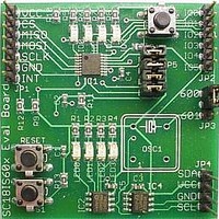
Interface Modules & Development Tools SPI to I2C Master Bridge Demoboard
Manufacturer
NXP Semiconductors
Datasheet
1.OM6271.pdf
(30 pages)
Specifications of OM6271
Interface Type
I2C, SPI
Data Bus Width
8 bit
For Use With/related Products
SC18IS601IPW
Lead Free Status / RoHS Status
Lead free / RoHS Compliant


NXP Semiconductors
SC18IS600_601_5
Product data sheet
Fig 17. Write after write
SPI host sends
COMMAND
0x03
NUMBER OF
BYTES 1
6.6.5 I
6.6.6 SPI configuration
When the host issues a Read Buffer command, the SC18IS600/601 will return the data in
the Read Buffer on the MISO pin. Note that the Read Buffer will be overwritten if an
additional ‘Read N bytes’ or a ‘Read after write’ command is executed before the Read
Buffer command.
When the host issues this command, the SC18IS600/601 will first write N data bytes to
the I
device.
Table 9.
The SPI configuration command can be used to change the order in which the bits of SPI
data byte are sent on the SPI bus. In the LSB first configuration (SPI configuration data is
0x81), bit 0 is the first bit sent of any SPI byte. In MSB first (SPI configuration data is
0x42), bit 7 is the first bit sent.
programmed.
SPI configuration
0x81
0x42
2
NUMBER OF
Fig 18. SPI configuration
C-bus write after write
BYTES 2
2
C-bus slave 1 device followed by a write of M data bytes to the I
SPI configuration
ADDRESS + W
SLAVE 1
SPI host sends
COMMAND
SCLK
MOSI
Rev. 05 — 28 July 2008
Data order
LSB first
MSB first (default)
0x18
CS
BYTE 1
DATA
Table 9
CONFIGURATION
character 0x18
SPI
shows the two possible configurations that can be
BYTE N
DATA
SPI configuration data
ADDRESS + W
SLAVE 2
SC18IS600/601
002aab722
SPI to I
BYTE 1
DATA
2
C-bus slave 2
© NXP B.V. 2008. All rights reserved.
2
C-bus interface
BYTE N
DATA
002aab721
15 of 30
Related parts for OM6271
Image
Part Number
Description
Manufacturer
Datasheet
Request
R

Part Number:
Description:
NXP Semiconductors designed the LPC2420/2460 microcontroller around a 16-bit/32-bitARM7TDMI-S CPU core with real-time debug interfaces that include both JTAG andembedded trace
Manufacturer:
NXP Semiconductors
Datasheet:

Part Number:
Description:
NXP Semiconductors designed the LPC2458 microcontroller around a 16-bit/32-bitARM7TDMI-S CPU core with real-time debug interfaces that include both JTAG andembedded trace
Manufacturer:
NXP Semiconductors
Datasheet:
Part Number:
Description:
NXP Semiconductors designed the LPC2468 microcontroller around a 16-bit/32-bitARM7TDMI-S CPU core with real-time debug interfaces that include both JTAG andembedded trace
Manufacturer:
NXP Semiconductors
Datasheet:
Part Number:
Description:
NXP Semiconductors designed the LPC2470 microcontroller, powered by theARM7TDMI-S core, to be a highly integrated microcontroller for a wide range ofapplications that require advanced communications and high quality graphic displays
Manufacturer:
NXP Semiconductors
Datasheet:
Part Number:
Description:
NXP Semiconductors designed the LPC2478 microcontroller, powered by theARM7TDMI-S core, to be a highly integrated microcontroller for a wide range ofapplications that require advanced communications and high quality graphic displays
Manufacturer:
NXP Semiconductors
Datasheet:
Part Number:
Description:
The Philips Semiconductors XA (eXtended Architecture) family of 16-bit single-chip microcontrollers is powerful enough to easily handle the requirements of high performance embedded applications, yet inexpensive enough to compete in the market for hi
Manufacturer:
NXP Semiconductors
Datasheet:
Part Number:
Description:
The XA-S3 device is a member of Philips Semiconductors? XA(eXtended Architecture) family of high performance 16-bitsingle-chip microcontrollers
Manufacturer:
NXP Semiconductors
Datasheet:

Part Number:
Description:
The NXP BlueStreak LH75401/LH75411 family consists of two low-cost 16/32-bit System-on-Chip (SoC) devices
Manufacturer:
NXP Semiconductors
Datasheet:
Part Number:
Description:
The NXP LPC3130/3131 combine an 180 MHz ARM926EJ-S CPU core, high-speed USB2
Manufacturer:
NXP Semiconductors
Datasheet:
Part Number:
Description:
The NXP LPC3141 combine a 270 MHz ARM926EJ-S CPU core, High-speed USB 2
Manufacturer:
NXP Semiconductors
Part Number:
Description:
The NXP LPC3143 combine a 270 MHz ARM926EJ-S CPU core, High-speed USB 2
Manufacturer:
NXP Semiconductors

Part Number:
Description:
The NXP LPC3152 combines an 180 MHz ARM926EJ-S CPU core, High-speed USB 2
Manufacturer:
NXP Semiconductors
Part Number:
Description:
The NXP LPC3154 combines an 180 MHz ARM926EJ-S CPU core, High-speed USB 2
Manufacturer:
NXP Semiconductors

Part Number:
Description:
Standard level N-channel enhancement mode Field-Effect Transistor (FET) in a plastic package using NXP High-Performance Automotive (HPA) TrenchMOS technology
Manufacturer:
NXP Semiconductors
Datasheet: