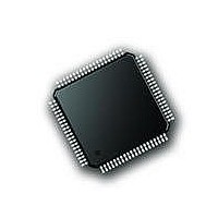
PIC18F87J72-I/PT Microchip Technology, PIC18F87J72-I/PT Datasheet - Page 438

PIC18F87J72-I/PT
Manufacturer Part Number
PIC18F87J72-I/PT
Description
IC PIC MCU 8BIT 14KB FLSH 80TQFP
Manufacturer
Microchip Technology
Series
PIC® 18Fr
Datasheet
1.PIC18F86J72-IPT.pdf
(480 pages)
Specifications of PIC18F87J72-I/PT
Program Memory Type
FLASH
Program Memory Size
128KB (64K x 16)
Package / Case
80-TQFP
Core Processor
PIC
Core Size
8-Bit
Speed
48MHz
Connectivity
I²C, LIN, SPI, UART/USART
Peripherals
Brown-out Detect/Reset, LCD, LVD, POR, PWM, WDT
Number Of I /o
51
Ram Size
3.8K x 8
Voltage - Supply (vcc/vdd)
2 V ~ 3.6 V
Data Converters
A/D 12x12b
Oscillator Type
Internal
Operating Temperature
-40°C ~ 85°C
Data Bus Width
8 bit
Data Ram Size
4 KB
Interface Type
SPI, USART, SPI, I2C
Maximum Clock Frequency
8 MHz
Number Of Programmable I/os
51
Number Of Timers
4
Operating Supply Voltage
2 V to 3.6 V
Maximum Operating Temperature
+ 85 C
Mounting Style
SMD/SMT
Minimum Operating Temperature
- 40 C
On-chip Adc
14
Controller Family/series
PIC18F
No. Of I/o's
51
Ram Memory Size
3923Byte
Cpu Speed
48MHz
No. Of Timers
4
Rohs Compliant
Yes
Lead Free Status / RoHS Status
Lead free / RoHS Compliant
Lead Free Status / RoHS Status
Lead free / RoHS Compliant, Lead free / RoHS Compliant
Available stocks
Company
Part Number
Manufacturer
Quantity
Price
Company:
Part Number:
PIC18F87J72-I/PT
Manufacturer:
Microchip
Quantity:
210
Company:
Part Number:
PIC18F87J72-I/PT
Manufacturer:
Microchip Technology
Quantity:
10 000
- Current page: 438 of 480
- Download datasheet (5Mb)
PIC18F87J72 FAMILY
B.3
This section defines the terms and formulas used
throughout this data sheet. The following terms are
defined:
• MCLK – Master Clock
• AMCLK – Analog Master Clock
• DMCLK – Digital Master Clock
• DRCLK – Data Rate Clock
• OSR – Oversampling Ratio
• Offset Error
• Gain Error
• Integral Non-Linearity Error
• Signal-To-Noise Ratio (SNR)
• Signal-To-Noise Ratio And Distortion (SINAD)
• Total Harmonic Distortion (THD)
• Spurious-Free Dynamic Range (SFDR)
• Idle Tones
• Dithering
• Crosstalk
• PSRR
• CMRR
• ADC Reset Mode
• Hard Reset Mode (ARESET = 0)
• ADC Shutdown Mode
• Full Shutdown Mode
B.3.1
This is the fastest clock present in the device. This is
the frequency of the clock input at the CLKIA.
B.3.2
This is the clock frequency that is present on the analog
portion of the device, after prescaling has occurred via
the CONFIG1 PRESCALE<1:0> register bits. The ana-
log portion includes the PGAs and the two sigma-delta
modulators.
EQUATION B-1:
DS39979A-page 438
Terminology and Formulas
MCLK – MASTER CLOCK
AMCLK – ANALOG MASTER CLOCK
AMCLK
=
------------------------------ -
PRESCALE
MCLK
Preliminary
TABLE B-1:
B.3.3
This is the clock frequency that is present on the digital
portion of the device, after prescaling and division by 4.
This is also the sampling frequency, that is the rate at
which the modulator outputs are refreshed. Each
period of this clock corresponds to one sample and one
modulator output.
EQUATION B-2:
B.3.4
This is the output data rate (i.e., the rate at which the
ADCs output new data). Each new data is signaled by
a data ready pulse on the DR pin.
This data rate is depending on the OSR and the
prescaler with the following formula:
EQUATION B-3:
Since this is the output data rate, and since the
decimation filter is a SINC (or notch) filter, there is a
notch in the filter transfer function at each integer
multiple of this rate.
Table B-2 describes the various combinations of OSR
and PRESCALE and their associated AMCLK, DMCLK
and DRCLK rates.
DRCLK
(CONFIG1<15:14>)
0
0
1
1
PRESCALE
DMCLK
=
DMCLK
--------------------- -
DMCLK – DIGITAL MASTER CLOCK
DRCLK – DATA RATE CLOCK
OSR
0
1
0
1
=
OVERSAMPLING RATIO
SETTINGS
AMCLK
-------------------- -
=
AMCLK
---------------------
4
4
2010 Microchip Technology Inc.
AMCLK = MCLK/1 (default)
OSR
Analog Master Clock
=
AMCLK = MCLK/2
AMCLK = MCLK/4
AMCLK = MCLK/8
=
--------------------------------------- -
4 PRESCALE
---------------------------------------------------------- -
4
Prescale
MCLK
OSR
MCLK
PRESCALE
Related parts for PIC18F87J72-I/PT
Image
Part Number
Description
Manufacturer
Datasheet
Request
R

Part Number:
Description:
Manufacturer:
Microchip Technology Inc.
Datasheet:

Part Number:
Description:
Manufacturer:
Microchip Technology Inc.
Datasheet:

Part Number:
Description:
Manufacturer:
Microchip Technology Inc.
Datasheet:

Part Number:
Description:
Manufacturer:
Microchip Technology Inc.
Datasheet:

Part Number:
Description:
Manufacturer:
Microchip Technology Inc.
Datasheet:

Part Number:
Description:
Manufacturer:
Microchip Technology Inc.
Datasheet:

Part Number:
Description:
Manufacturer:
Microchip Technology Inc.
Datasheet:

Part Number:
Description:
Manufacturer:
Microchip Technology Inc.
Datasheet:


