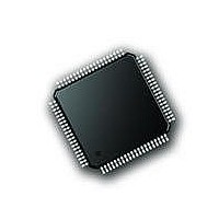
PIC18F87J72-I/PT Microchip Technology, PIC18F87J72-I/PT Datasheet - Page 154

PIC18F87J72-I/PT
Manufacturer Part Number
PIC18F87J72-I/PT
Description
IC PIC MCU 8BIT 14KB FLSH 80TQFP
Manufacturer
Microchip Technology
Series
PIC® 18Fr
Datasheet
1.PIC18F86J72-IPT.pdf
(480 pages)
Specifications of PIC18F87J72-I/PT
Program Memory Type
FLASH
Program Memory Size
128KB (64K x 16)
Package / Case
80-TQFP
Core Processor
PIC
Core Size
8-Bit
Speed
48MHz
Connectivity
I²C, LIN, SPI, UART/USART
Peripherals
Brown-out Detect/Reset, LCD, LVD, POR, PWM, WDT
Number Of I /o
51
Ram Size
3.8K x 8
Voltage - Supply (vcc/vdd)
2 V ~ 3.6 V
Data Converters
A/D 12x12b
Oscillator Type
Internal
Operating Temperature
-40°C ~ 85°C
Data Bus Width
8 bit
Data Ram Size
4 KB
Interface Type
SPI, USART, SPI, I2C
Maximum Clock Frequency
8 MHz
Number Of Programmable I/os
51
Number Of Timers
4
Operating Supply Voltage
2 V to 3.6 V
Maximum Operating Temperature
+ 85 C
Mounting Style
SMD/SMT
Minimum Operating Temperature
- 40 C
On-chip Adc
14
Controller Family/series
PIC18F
No. Of I/o's
51
Ram Memory Size
3923Byte
Cpu Speed
48MHz
No. Of Timers
4
Rohs Compliant
Yes
Lead Free Status / RoHS Status
Lead free / RoHS Compliant
Lead Free Status / RoHS Status
Lead free / RoHS Compliant, Lead free / RoHS Compliant
Available stocks
Company
Part Number
Manufacturer
Quantity
Price
Company:
Part Number:
PIC18F87J72-I/PT
Manufacturer:
Microchip
Quantity:
210
Company:
Part Number:
PIC18F87J72-I/PT
Manufacturer:
Microchip Technology
Quantity:
10 000
- Current page: 154 of 480
- Download datasheet (5Mb)
PIC18F87J72 FAMILY
15.3.2
At every alarm event, an interrupt is generated. Addi-
tionally, an alarm pulse output is provided that operates
at half the frequency of the alarm.
The alarm pulse output is completely synchronous with
the RTCC clock and can be used as a trigger clock to
other peripherals. This output is available on the RTCC
pin. The output pulse is a clock with a 50% duty cycle
and a frequency half that of the alarm event (see
Figure 15-6).
FIGURE 15-6:
15.4
The timer and alarm continue to operate while in Sleep
mode. The operation of the alarm is not affected by
Sleep as an alarm event can always wake-up the CPU.
The Idle mode does not affect the operation of the timer
or alarm.
15.5
15.5.1
When a device Reset occurs, the ALCFGRPT register
is forced to its Reset state, causing the alarm to be
disabled (if enabled prior to the Reset). If the RTCC
was enabled, it will continue to operate when a basic
device Reset occurs.
DS39979A-page 154
RTCC Alarm Event
Sleep Mode
Reset
ALRMEN bit
ALARM INTERRUPT
DEVICE RESET
RTCEN bit
RTCC Pin
TIMER PULSE GENERATION
Preliminary
The RTCC pin can also output the seconds clock. The
user can select between the alarm pulse, generated by
the RTCC module, or the seconds clock output.
The RTSECSEL<1:0> (PADCFG1<2:1>) bits select
between these two outputs:
• Alarm Pulse – RTSECSEL<1:0> = 00
• Seconds Clock – RTSECSEL<1:0> = 01
15.5.2
The RTCCFG and ALRMRPT registers are reset only
on a POR. Once the device exits the POR state, the
clock registers should be reloaded with the desired
values.
The timer prescaler values can be reset only by writing
to the SECONDS register. No device Reset can affect
the prescalers.
POWER-ON RESET (POR)
2010 Microchip Technology Inc.
Related parts for PIC18F87J72-I/PT
Image
Part Number
Description
Manufacturer
Datasheet
Request
R

Part Number:
Description:
Manufacturer:
Microchip Technology Inc.
Datasheet:

Part Number:
Description:
Manufacturer:
Microchip Technology Inc.
Datasheet:

Part Number:
Description:
Manufacturer:
Microchip Technology Inc.
Datasheet:

Part Number:
Description:
Manufacturer:
Microchip Technology Inc.
Datasheet:

Part Number:
Description:
Manufacturer:
Microchip Technology Inc.
Datasheet:

Part Number:
Description:
Manufacturer:
Microchip Technology Inc.
Datasheet:

Part Number:
Description:
Manufacturer:
Microchip Technology Inc.
Datasheet:

Part Number:
Description:
Manufacturer:
Microchip Technology Inc.
Datasheet:


