FPDB40PH60B Fairchild Semiconductor, FPDB40PH60B Datasheet
FPDB40PH60B
Specifications of FPDB40PH60B
Available stocks


Related parts for FPDB40PH60B


FPDB40PH60B Summary of contents
Page 1
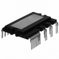
... FPDB40PH60B Smart Power Module for Front-End Rectifier General Description FPDB40PH60B is an advanced smart power module of PFC(Power Factor Correction) that Fairchild has newly developed and designed mainly targeting mid-power application especially for an air conditioners. It combines optimized circuit protection and drive IC matched to high frequency switching IGBTs ...
Page 2
... NC (17) NC (17) NC (17) NC (18) NC (18) NC (18) NC (18) NC (19) R (19) R (19) R (19 (20) V (20) V (20) V (20 ©2009 Fairchild Semiconductor Corporation Top View (21) V (21) V (21) V (21) V AC- AC- AC- AC- (22) N (22) N (22) N (22) N SENSE SENSE SENSE SENSE (23) N (23) N (23) NC (23) NC (24) N (24) N (24) N ...
Page 3
... V VFO FO (5) IN IN(S) (S) (4) IN IN(R) (R) (2) COM COM (1) VCC VCC Note : 1) Converter is composed of two IGBTs including four diodes and one IC which has gate driving and protection functions. ©2009 Fairchild Semiconductor Corporation Pin Description NTC Therm istor D1 OUT( OUT(R) Fig. 3. (27 (26) S ...
Page 4
... Symbol Junction to Case Thermal R θ (j-c)Q Resistance R θ (j-c)HD (Referenced to PKG cen- R θ (j-c)LD ter) Note : 2. For the measurement point of case temperature(T ©2009 Fairchild Semiconductor Corporation (T = 25°C, Unless Otherwise Specified) J Symbol Condition V Applied between R Applied between R-S i(Surge) V Applied between P- N ...
Page 5
... Recommended Operating conditions Item Symbol Input Supply Voltage V I Output Voltage V PN Control Supply Voltage V CC Control Supply Variation dV /dt Applied between IN - COM CC PWM Input Signal f PWM ©2009 Fairchild Semiconductor Corporation (T = 25°C, Unless Otherwise Specified) J Condition V =15V 5V; I =40A 40A 40A F V ...
Page 6
... Electrical Characteristics 100 90 10 (a) Turn-on Mechanical Characteristics and Ratings Item Mounting Torque Mounting Screw Device Flatness Note Fig. 5 Weight ©2009 Fairchild Semiconductor Corporation I rr 120 10 10 C(ON) OFF Fig. 4. Switching Time Definition Condition Recommended 0.62N•m (+) (+) Fig. 5. Flatness Measurement Position 10 C(OFF) ...
Page 7
... P2 : Over current detection P3 : IGBT gate interrupt / Fault signal generation P4 : IGBT is slowly turned off P5 : IGBT OFF signal P6 : IGBT ON signal - but IGBT cannot be turned on during the fault Output activation P7 : IGBT OFF state P8 : Fault Output reset and normal operation start ©2009 Fairchild Semiconductor Corporation Fig ...
Page 8
... Microcontroller or DSP Note : 1) For the over-current protection, please set the delay time in the range 3~4μs. 120 100 ©2009 Fairchild Semiconductor Corporation PFCM V TH NTC R Thermistor CSC C FOD CFOD V FO VFO OUT(S) IN (S) IN(S) IN (R) IN(R) OUT(R) COM COM VCC VCC Fig ...
Page 9
... Detailed Package Outline Drawings ©2009 Fairchild Semiconductor Corporation February, 2009 ...
Page 10
... Detailed Package Outline Drawings ©2009 Fairchild Semiconductor Corporation February, 2009 ...
Page 11
... Detailed Package Outline Drawings ©2009 Fairchild Semiconductor Corporation February, 2009 ...
Page 12
... TRADEMARKS The following are registered and unregistered trademarks Fairchild Semiconductor owns or is authorized to use and is not intended exhaustive list of all such trademarks. ACEx™ FAST Bottomless™ FASTr™ CoolFET™ GlobalOptoisolator™ CROSSVOLT™ GTO™ DenseTrench™ HiSeC™ ...