AT88RF1354-ZU Atmel, AT88RF1354-ZU Datasheet - Page 41
AT88RF1354-ZU
Manufacturer Part Number
AT88RF1354-ZU
Description
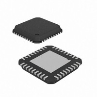
IC RF READER 13.56MHZ 36-VQFN
Manufacturer
Atmel
Datasheet
1.AT88RF1354-ZU.pdf
(48 pages)
Specifications of AT88RF1354-ZU
Frequency
13.56MHz
Features
ISO14443-B
Package / Case
36-VQFN Exposed Pad, 36-HVQFN, 36-SQFN, 36-DHVQFN
Pin Count
36
Screening Level
Industrial
Lead Free Status / RoHS Status
Lead free / RoHS Compliant
Rf Type
-
Lead Free Status / Rohs Status
Compliant


D.6.
D.6.1. Component Removal
8547B–RFID–3/09
Figure D-9. Typical PCB mounting process flow.
Rework Guidelines
Since solder joints are not fully exposed in the case of QFNs, any retouch is limited to the side fillet. For defects
underneath the package, the whole package has to be removed. Rework of the QFN packages can be a challenge due
to their small size. In most applications, the QFNs will be mounted on smaller, thinner, and denser PCBs that introduce
further challenges due to the handling and the heating issues. Since reflow of the adjacent parts is not desirable during
rework, the proximity of other components may further complicate this process. Because of the product dependent
complexities, the following only provides a guideline and a starting point for the development of a successful rework
process for these packages.
The rework process involves the following steps:
These steps are discussed in the following in more detail. Prior to any rework, it is strongly recommended that the PCB
assembly be baked for at least 4 hours at 125 °C to remove any residual moisture from the assembly.
The first step in removal of the component is the reflow of the solder joints attaching the component to the board.
Ideally, the reflow profile for the part removal should be the same as the one used for the part attachment. However,
the time above liquidus can be reduced as long as the reflow is complete.
In the removal process, it is recommended that the board should be heated from the bottom side using convective
heaters and hot gas or air should be used on the top side of the component. Special nozzles should be used to direct
the heating in the component area and the heating of adjacent components should be minimized. Excessive airflow
should also be avoided since this may cause the package to skew. Air velocity of 15-20 liters per minute is a good
starting point.
Once the joints have reflowed, the vacuum lift-off should be automatically engaged during the transition from the reflow
to cool down. Because of their small size the vacuum pressure should be kept below 15 inches of Hg. This will allow
the component not to be lifted off if all joints have not been reflowed and avoid pad damage.
Component Placement
Pre Reflow Inspection
Solder Paste Printing
Post Print Inspection
1.
2.
3.
4.
5.
Component Removal
Site Redress
Solder Paste Application,
Component Placement, and
Component Attachment.
13.56 MHz Type B RF Reader Specification
Post Reflow Inspection
Rework & Touch Up
(Visual/X-ray)
REFLOW
41
Related parts for AT88RF1354-ZU
Image
Part Number
Description
Manufacturer
Datasheet
Request
R

Part Number:
Description:
DEV KIT FOR AVR/AVR32
Manufacturer:
Atmel
Datasheet:

Part Number:
Description:
INTERVAL AND WIPE/WASH WIPER CONTROL IC WITH DELAY
Manufacturer:
ATMEL Corporation
Datasheet:
Part Number:
Description:
Low-Voltage Voice-Switched IC for Hands-Free Operation
Manufacturer:
ATMEL Corporation
Datasheet:
Part Number:
Description:
MONOLITHIC INTEGRATED FEATUREPHONE CIRCUIT
Manufacturer:
ATMEL Corporation
Datasheet:
Part Number:
Description:
AM-FM Receiver IC U4255BM-M
Manufacturer:
ATMEL Corporation
Datasheet:
Part Number:
Description:
Monolithic Integrated Feature Phone Circuit
Manufacturer:
ATMEL Corporation
Datasheet:
Part Number:
Description:
Multistandard Video-IF and Quasi Parallel Sound Processing
Manufacturer:
ATMEL Corporation
Datasheet:
Part Number:
Description:
High-performance EE PLD
Manufacturer:
ATMEL Corporation
Datasheet:
Part Number:
Description:
8-bit Flash Microcontroller
Manufacturer:
ATMEL Corporation
Datasheet:
Part Number:
Description:
2-Wire Serial EEPROM
Manufacturer:
ATMEL Corporation
Datasheet: