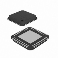
AT88RF1354-ZU Atmel, AT88RF1354-ZU Datasheet - Page 20

AT88RF1354-ZU
Manufacturer Part Number
AT88RF1354-ZU
Description
IC RF READER 13.56MHZ 36-VQFN
Manufacturer
Atmel
Datasheet
1.AT88RF1354-ZU.pdf
(48 pages)
Specifications of AT88RF1354-ZU
Frequency
13.56MHz
Features
ISO14443-B
Package / Case
36-VQFN Exposed Pad, 36-HVQFN, 36-SQFN, 36-DHVQFN
Pin Count
36
Screening Level
Industrial
Lead Free Status / RoHS Status
Lead free / RoHS Compliant
Rf Type
-
Lead Free Status / Rohs Status
Compliant
7.
7.1.
7.2.
20
Typical Characteristics
The performance of AT88RF1354 is dependent on the reader circuit, the loop antenna design, the board layout, the
specifications of the passive components, the quality of the supply voltages, the quality of the ground, the electrical
noise in the system, and how the reader circuit is connected to the other system components. The specifications that
are affected by these factors are included in this section as typical characteristics since they cannot be guaranteed in
all situations.
It is recommended that AT88RF1354 be used exactly as described in the reference designs in the AT88RF1354
Application Notes. Each reference design has been optimized for reliable, robust communications with cards and tags
with antenna dimensions within a specified size range. The reference designs described in the AT88RF1354
Application Notes include schematics, board designs, and a complete bill of materials. Gerber files of the PCB layout
are available.
Atmel does not provide applications engineering support for customer implementations that deviate from the reference
designs; it is strongly recommended that the AT88RF1354 reference designs be implemented exactly as provided. Any
modification to the board layout or deviation from the bill of materials will impact both electrical performance and
radiated emissions.
Supply Current
T
Note:
Standby Current
T
Note:
13.56 MHz Type B RF Reader Specification
C
ICC
ICC_ANT
C
ISB
ISB_ANT
= -40° to +85° C (unless otherwise noted)
Symbol
= -40° to +85° C (unless otherwise noted)
Symbol
1. Typical values at Tc = 35° C. Values are based on characterization and are not tested.
2. The total D.C. supply current is ICC + ICC_ANT
3. Supply current is dependent on the reader circuit design, PCB layout, and component specifications.
4. ICC_ANT current increases rapidly when the RF ON Command is sent. The rate of ICC_ANT current
1. Typical values at Tc = 35° C. Values are based on characterization and are not tested.
2. Total power supply standby current is ISB + ISB_ANT
3. The Sleep Command is sent to enter standby mode. All serial interface signals must remain unchanged to
4. PLL Register bits control standby mode options: ENB controls CLKO, SL1 controls PLL, SL2 controls
5. Supply current is dependent on the reader circuit design, PCB layout, and component specifications. All
Power Supply Current
Power Supply Current
All values in table measured on an Atmel reference design.
change is the slew rate.
Power Supply Standby Current
Power Supply Standby Current
remain in standby mode.
OSC (crystal oscillator)
values in table measured on an Atmel reference design.
Parameter
Parameter
Idle, No SCK clock, CLKO Disabled
Idle, RF Disabled
Idle, RF Enabled (TXP = 1 b)
Standby, CLKO Disabled, OSC and PLL Enabled
Standby, CLKO Enabled, OSC and PLL Enabled
Standby, CLKO Disabled, OSC and PLL Enabled
(1)
(1)
Condition
Condition
Min Typical
V
CC
3.0 to 3.6 V
and V
200
10
1
V
Min Typical
CC_ANT
CC
3.0 to 3.6 V
Max
and V
=
10
2
1
CC_ANT
Min
V
Max
CC
=
4.5 to 5.5 V
and V
Typical
Min Typical
250
V
15
2
= 4.5 to 5.5 V
CC
CC_ANT
and V
15
3
2
8547B–RFID–3/09
Max
=
CC_ANT
Max
Units
mA
mA
mA
Units
mA
mA
mA


