AT88RF1354-ZU Atmel, AT88RF1354-ZU Datasheet - Page 15
AT88RF1354-ZU
Manufacturer Part Number
AT88RF1354-ZU
Description
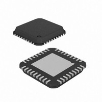
IC RF READER 13.56MHZ 36-VQFN
Manufacturer
Atmel
Datasheet
1.AT88RF1354-ZU.pdf
(48 pages)
Specifications of AT88RF1354-ZU
Frequency
13.56MHz
Features
ISO14443-B
Package / Case
36-VQFN Exposed Pad, 36-HVQFN, 36-SQFN, 36-DHVQFN
Pin Count
36
Screening Level
Industrial
Lead Free Status / RoHS Status
Lead free / RoHS Compliant
Rf Type
-
Lead Free Status / Rohs Status
Compliant


5.2.
8547B–RFID–3/09
Application
In a typical application the AT88RF1354 reader circuitry and the loop antenna are integrated on a single four layer
printed circuit board. The host microcontroller and power supply may reside on the same PCB, or on a separate PCB
depending on the application requirements.
The passive components required for the reader IC to function are placed in a small area immediately surrounding the
QFN package for optimum RF circuit performance. The PCB loop antenna is placed a minimum of 1 inch away from all
other metal, including the reader circuit ground and power planes, to minimize distortion of the magnetic field which
reduces RF communication performance. A typical loop antenna is designed for an inductance of 800 to 1600
nanohenries, DC resistance of 0.1 to 0.3 ohms, low parasitic capacitance, and includes a matching electric field shield.
Whether the power supply and microcontroller are integrated in the same board or are on a different board, power
filtering is included at the edge of the reader circuit ground and power planes to isolate the reader from in-band system
noise and to protect the host microcontroller from reader generated noise. The reader ground and power planes must
be isolated from the balance of the system to prevent current loops from forming which will interfere with RF tag
performance.
Layout of both the reader circuitry and loop antenna are critical, and are beyond the scope of this document. See the
reference designs in the AT88RF1354 Application Notes for layout and circuit recommendations.
Figure 4.
Typical AT88RF1354 Reader board layout
Microcontroller
Power Supply
Circuit
13.56 MHz Type B RF Reader Specification
Reader
Circuit
Antenna
Loop
15
Related parts for AT88RF1354-ZU
Image
Part Number
Description
Manufacturer
Datasheet
Request
R

Part Number:
Description:
DEV KIT FOR AVR/AVR32
Manufacturer:
Atmel
Datasheet:

Part Number:
Description:
INTERVAL AND WIPE/WASH WIPER CONTROL IC WITH DELAY
Manufacturer:
ATMEL Corporation
Datasheet:
Part Number:
Description:
Low-Voltage Voice-Switched IC for Hands-Free Operation
Manufacturer:
ATMEL Corporation
Datasheet:
Part Number:
Description:
MONOLITHIC INTEGRATED FEATUREPHONE CIRCUIT
Manufacturer:
ATMEL Corporation
Datasheet:
Part Number:
Description:
AM-FM Receiver IC U4255BM-M
Manufacturer:
ATMEL Corporation
Datasheet:
Part Number:
Description:
Monolithic Integrated Feature Phone Circuit
Manufacturer:
ATMEL Corporation
Datasheet:
Part Number:
Description:
Multistandard Video-IF and Quasi Parallel Sound Processing
Manufacturer:
ATMEL Corporation
Datasheet:
Part Number:
Description:
High-performance EE PLD
Manufacturer:
ATMEL Corporation
Datasheet:
Part Number:
Description:
8-bit Flash Microcontroller
Manufacturer:
ATMEL Corporation
Datasheet:
Part Number:
Description:
2-Wire Serial EEPROM
Manufacturer:
ATMEL Corporation
Datasheet: