AT88RF1354-ZU Atmel, AT88RF1354-ZU Datasheet - Page 34
AT88RF1354-ZU
Manufacturer Part Number
AT88RF1354-ZU
Description
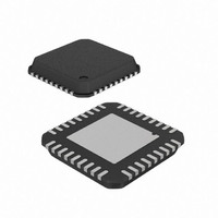
IC RF READER 13.56MHZ 36-VQFN
Manufacturer
Atmel
Datasheet
1.AT88RF1354-ZU.pdf
(48 pages)
Specifications of AT88RF1354-ZU
Frequency
13.56MHz
Features
ISO14443-B
Package / Case
36-VQFN Exposed Pad, 36-HVQFN, 36-SQFN, 36-DHVQFN
Pin Count
36
Screening Level
Industrial
Lead Free Status / RoHS Status
Lead free / RoHS Compliant
Rf Type
-
Lead Free Status / Rohs Status
Compliant


D.3.
D.3.1. Perimeter Pads Design
D.3.2. Thermal Pad and Via Design
D.3.3. Solder Masking Consideration
34
PCB Design Guidelines
As shown in Figure D-1. the lands on the package bottom side are rectangular in shape with rounded edges on the
inside. Since the package does not have any solder balls, the electrical connection between the package and the board
is made by printing the solder paste on the board and reflowing it after the component placement. In order to form
reliable solder joints, special attention is needed in designing the board pad pattern and the solder paste printing.
Typically the PCB pad pattern for a package is designed based on guidelines developed within a company or by
following industry standards such as IPC-SM-782. However, since the QFN is a new package and the industry
guidelines have not been developed yet for a PCB pad pattern design, the development of proper design
considerations may require some experimental trials.
IPC’s methodology is used here for designing the PCB pad pattern. However, because of the exposed die paddle and
the package lands on the bottom side of the package, certain constraints are added to IPC’s methodology. The pad
pattern developed here includes considerations for lead and package tolerances.
The QFN package is designed to provide superior thermal performance. This is partly achieved by incorporating an
exposed die paddle on the bottom surface of the package. However, in order to take full advantage of this feature, the
PCB must have features to effectively conduct heat away from the package. This can be achieved by incorporating a
thermal pad and thermal vias on the PCB. While a thermal pad provides a solderable surface on the top surface of the
PCB (to solder the package die paddle on the board), the thermal vias are needed to provide a thermal path to the
inner and bottom layers of the PCB to remove the heat.
Normally, the size of the thermal pad should at least match the exposed die paddle size. However, depending upon the
die paddle size, this size needs to be modified in some cases to avoid solder bridging between the thermal pad and the
perimeter pads. The thermal pad design on the board should be based on the exposed paddle area, excluding the ring
area.
In order to effectively transfer heat from the top metal layer of the PCB to the inner and bottom layers, thermal vias
need to be incorporated into the thermal pad design. The number of thermal vias will depend on the application, the
power dissipation, and the electrical requirements. It is recommended that an array of thermal vias should be
incorporated at a 1.0 to 1.2 mm pitch with a via diameter of 0.3 to 0.33 mm.
recommended that a minimum of nine vias be placed in the thermal pad, and a 1 ounce copper thickness be used on
all PCB layers on AT88RF1354 readers.
The pads on the printed circuit board are either solder mask defined (SMD) or non solder mask defined (NSMD). Since
the copper etching process has tighter control than the solder masking process, NSMD pads are preferred over SMD
pads. Also, NSMD pads with the solder mask opening larger than the metal pad size improves the reliability of the
solder joints, as solder is allowed to wrap around the sides of the metal pads. For these reasons, the NSMD pad is
recommended for perimeter lands.
The solder mask opening should be 120 to 150 microns larger than the pad size resulting in 60 to 75 micron clearance
between the copper pad and the solder mask. This allows for solder mask registration tolerances, which are typically
between 50 to 65 microns, depending upon the board fabricators' capabilities. Typically each pad on the PCB should
have its own solder mask opening with a web of solder mask between the two adjacent pads. Since the web has to be
at least 75 microns in width for the solder mask to stick to the PCB surface, each pad can have its own solder mask
opening for a lead pitch of 0.5 mm or higher. However, for finer pitch parts, not enough space is available for the solder
mask web in between the pads. In such cases, it is recommended to use the “trench” type solder mask opening where
a big opening is designed around all the pads on each side of the package with no solder mask in between the pads,
as shown in Figure D-2. It should also be noted that the inner edge of the solder mask should be rounded, especially
for the corner leads to allow for enough solder mask web in the corner area.
13.56 MHz Type B RF Reader Specification
For optimum heat transfer it is
8547B–RFID–3/09
Related parts for AT88RF1354-ZU
Image
Part Number
Description
Manufacturer
Datasheet
Request
R

Part Number:
Description:
DEV KIT FOR AVR/AVR32
Manufacturer:
Atmel
Datasheet:

Part Number:
Description:
INTERVAL AND WIPE/WASH WIPER CONTROL IC WITH DELAY
Manufacturer:
ATMEL Corporation
Datasheet:
Part Number:
Description:
Low-Voltage Voice-Switched IC for Hands-Free Operation
Manufacturer:
ATMEL Corporation
Datasheet:
Part Number:
Description:
MONOLITHIC INTEGRATED FEATUREPHONE CIRCUIT
Manufacturer:
ATMEL Corporation
Datasheet:
Part Number:
Description:
AM-FM Receiver IC U4255BM-M
Manufacturer:
ATMEL Corporation
Datasheet:
Part Number:
Description:
Monolithic Integrated Feature Phone Circuit
Manufacturer:
ATMEL Corporation
Datasheet:
Part Number:
Description:
Multistandard Video-IF and Quasi Parallel Sound Processing
Manufacturer:
ATMEL Corporation
Datasheet:
Part Number:
Description:
High-performance EE PLD
Manufacturer:
ATMEL Corporation
Datasheet:
Part Number:
Description:
8-bit Flash Microcontroller
Manufacturer:
ATMEL Corporation
Datasheet:
Part Number:
Description:
2-Wire Serial EEPROM
Manufacturer:
ATMEL Corporation
Datasheet: