AT88RF1354-ZU Atmel, AT88RF1354-ZU Datasheet - Page 40
AT88RF1354-ZU
Manufacturer Part Number
AT88RF1354-ZU
Description
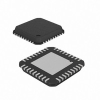
IC RF READER 13.56MHZ 36-VQFN
Manufacturer
Atmel
Datasheet
1.AT88RF1354-ZU.pdf
(48 pages)
Specifications of AT88RF1354-ZU
Frequency
13.56MHz
Features
ISO14443-B
Package / Case
36-VQFN Exposed Pad, 36-HVQFN, 36-SQFN, 36-DHVQFN
Pin Count
36
Screening Level
Industrial
Lead Free Status / RoHS Status
Lead free / RoHS Compliant
Rf Type
-
Lead Free Status / Rohs Status
Compliant


D.4.6. Reflow Profile
D.5.
40
The reflow profile and the peak temperature have a strong influence on void formation. Amkor has conducted
experiments with the different reflow profiles (ramp-to-peak vs. ramp-hold-ramp), the peak reflow temperatures, and the
times above liquidus using Alpha Metal’s UP78 solder paste. Some of the representative profiles are shown in Figure
D-8. Generally, it is found that the 37% paste coverage, plugged via, voids in the thermal pad region for the plugged
vias reduce as the peak reflow temperature is increased from 210 °C to 215-220 °C. For the encroached vias, it is
found that the solder extrusion from the bottom side of the board reduces as the reflow temperature is reduced.
Figure D-8. Various QFN solder reflow profiles.
Assembly Process Flow
Figure D-9. shows the typical process flow for mounting surface mount packages to printed circuit boards. The same
process can be used for mounting the QFNs without any modifications. It is important to include the post print and the
post reflow inspection, especially during the process development. The volume of paste printed should be measured
either by 2D or 3D techniques. The paste volume should be around 80 to 90% of the stencil aperture volume to indicate
a good paste release. After reflow, the mounted package should be inspected in the transmission x-ray for the
presence of voids, solder balling, or other defects. Cross-sectioning may also be required to determine the fillet shape,
size and the joint standoff height during process development. Typical reflow profiles for no-clean solder paste are
shown in Figure D-9.
Since the actual reflow profile depends on the solder paste being used and the board density, Atmel does not
recommend a specific profile. However, the temperature should not exceed the maximum temperature the package is
qualified for according to the moisture sensitivity level. The time above the liquidus temperature should be around 60
seconds and the ramp rate during preheat should be 3 °C/second or lower.
13.56 MHz Type B RF Reader Specification
Ramp-Soak-Spike – 210°C Peak
Ramp-Soak-Spike – 215°C Peak
Ramp-Spike – 210°C Peak
Ramp-Spike – 220°C Peak
8547B–RFID–3/09
Related parts for AT88RF1354-ZU
Image
Part Number
Description
Manufacturer
Datasheet
Request
R

Part Number:
Description:
DEV KIT FOR AVR/AVR32
Manufacturer:
Atmel
Datasheet:

Part Number:
Description:
INTERVAL AND WIPE/WASH WIPER CONTROL IC WITH DELAY
Manufacturer:
ATMEL Corporation
Datasheet:
Part Number:
Description:
Low-Voltage Voice-Switched IC for Hands-Free Operation
Manufacturer:
ATMEL Corporation
Datasheet:
Part Number:
Description:
MONOLITHIC INTEGRATED FEATUREPHONE CIRCUIT
Manufacturer:
ATMEL Corporation
Datasheet:
Part Number:
Description:
AM-FM Receiver IC U4255BM-M
Manufacturer:
ATMEL Corporation
Datasheet:
Part Number:
Description:
Monolithic Integrated Feature Phone Circuit
Manufacturer:
ATMEL Corporation
Datasheet:
Part Number:
Description:
Multistandard Video-IF and Quasi Parallel Sound Processing
Manufacturer:
ATMEL Corporation
Datasheet:
Part Number:
Description:
High-performance EE PLD
Manufacturer:
ATMEL Corporation
Datasheet:
Part Number:
Description:
8-bit Flash Microcontroller
Manufacturer:
ATMEL Corporation
Datasheet:
Part Number:
Description:
2-Wire Serial EEPROM
Manufacturer:
ATMEL Corporation
Datasheet: