AT88RF1354-ZU Atmel, AT88RF1354-ZU Datasheet - Page 35
AT88RF1354-ZU
Manufacturer Part Number
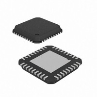
AT88RF1354-ZU
Description
IC RF READER 13.56MHZ 36-VQFN
Manufacturer
Atmel
Datasheet
1.AT88RF1354-ZU.pdf
(48 pages)
Specifications of AT88RF1354-ZU
Frequency
13.56MHz
Features
ISO14443-B
Package / Case
36-VQFN Exposed Pad, 36-HVQFN, 36-SQFN, 36-DHVQFN
Pin Count
36
Screening Level
Industrial
Lead Free Status / RoHS Status
Lead free / RoHS Compliant
Rf Type
-
Lead Free Status / Rohs Status
Compliant


D.4.
D.4.1. Stencil Design for Perimeter Pads
8547B–RFID–3/09
Figure D-2. Solder mask definition for perimeter lands.
For the cases where the thermal land dimensions are close to the theoretical maximum discussed above, it is
recommended that the thermal pad area should be solder mask defined in order to avoid any solder bridging between
the thermal pad and the perimeter pads. The mask opening should be 100 microns smaller than the thermal land size
on all four sides. This will guarantee a 25 micron solder mask overlap even for the worse case misregistration.
Board Mounting Guidelines
Due to the small lead surface area and the sole reliance on the printed solder paste on the PCB surface, care must be
taken to form reliable solder joints for QFN packages. This is further complicated by the large thermal pad underneath
the package and its proximity to the inner edges of the leads. Although the pad pattern design suggested above might
help in eliminating some of the surface mounting problems, special considerations are needed in the stencil design and
the paste printing for both the perimeter and the thermal pads. Since the surface mount process varies from company
to company, careful process development is recommended. The following provides some guidelines for the stencil
design based on Atmel’s experience in the surface mounting of QFN packages.
Optimum and reliable solder joints on the perimeter pads should have about 50 to 75 microns (2 to 3 mils) standoff
height and a good side fillet on the outside. A joint with good stand-off height but no or low fillet will have reduced life
but may meet the application requirement. The first step in achieving good standoff is the solder paste stencil design
for the perimeter pads. The stencil aperture opening should be designed so that maximum paste release is achieved.
This is typically accomplished by considering the following two ratios:
For rectangular aperture openings, as required for this package, these ratios are given as:
Where L and W are the aperture length and width, and T is stencil thickness. For optimum paste release the area and
the aspect ratios should be greater than 0.66 and 1.5 respectively. It is recommended that the stencil aperture should
be 1:1 to the PCB pad sizes as both the area and the aspect ratio targets are easily achieved by this aperture. The
opening can be reduced for a lead pullback option because of the reduction of the solderable area on the package.
The stencil should be laser cut and electro polished. The polishing helps in smoothing the stencil walls which results in
a better paste release. It is also recommended that the stencil aperture tolerances should be tightly controlled,
especially for 0.5mm pitch and finer devices, as these tolerances can effectively reduce the aperture size.
0.5 mm and Higher Pitch Parts
─ Area Ratio
─ Aspect Ratio
─ Area Ratio
─ Aspect Ratio
=
=
=
=
Area of Aperture Opening / Aperture Wall Area
Aperture width / Stencil Thickness
LW / 2T(L+W)
W / T
13.56 MHz Type B RF Reader Specification
Solder Mask
0.4 mm Pitch Parts
35
Related parts for AT88RF1354-ZU
Image
Part Number
Description
Manufacturer
Datasheet
Request
R

Part Number:
Description:
DEV KIT FOR AVR/AVR32
Manufacturer:
Atmel
Datasheet:

Part Number:
Description:
INTERVAL AND WIPE/WASH WIPER CONTROL IC WITH DELAY
Manufacturer:
ATMEL Corporation
Datasheet:
Part Number:
Description:
Low-Voltage Voice-Switched IC for Hands-Free Operation
Manufacturer:
ATMEL Corporation
Datasheet:
Part Number:
Description:
MONOLITHIC INTEGRATED FEATUREPHONE CIRCUIT
Manufacturer:
ATMEL Corporation
Datasheet:
Part Number:
Description:
AM-FM Receiver IC U4255BM-M
Manufacturer:
ATMEL Corporation
Datasheet:
Part Number:
Description:
Monolithic Integrated Feature Phone Circuit
Manufacturer:
ATMEL Corporation
Datasheet:
Part Number:
Description:
Multistandard Video-IF and Quasi Parallel Sound Processing
Manufacturer:
ATMEL Corporation
Datasheet:
Part Number:
Description:
High-performance EE PLD
Manufacturer:
ATMEL Corporation
Datasheet:
Part Number:
Description:
8-bit Flash Microcontroller
Manufacturer:
ATMEL Corporation
Datasheet:
Part Number:
Description:
2-Wire Serial EEPROM
Manufacturer:
ATMEL Corporation
Datasheet: