RXM-GPS-SG-T Linx Technologies Inc, RXM-GPS-SG-T Datasheet - Page 16
RXM-GPS-SG-T
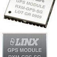
Manufacturer Part Number
RXM-GPS-SG-T
Description
GPS MODULE SMD SIRF
Manufacturer
Linx Technologies Inc
Series
SGr
Type
GPS Moduler
Datasheet
1.MDEV-GPS-SG.pdf
(17 pages)
Specifications of RXM-GPS-SG-T
Package / Case
Module
Operating Voltage
4.2 V
Operating Current
46 mA
Frequency Range
1575.42 MHz
Interface Type
UART, USB
Operating Temperature Range
- 30 C to + 85 C
Lead Free Status / RoHS Status
Lead free / RoHS Compliant
Features
-
Voltage - Supply
-
Frequency
-
Operating Temperature
-
Applications
-
Sensitivity
-
Memory Size
-
Data Interface
-
Data Rate - Maximum
-
Modulation Or Protocol
-
Antenna Connector
-
Current - Receiving
-
Lead Free Status / Rohs Status
Lead free / RoHS Compliant


PAD LAYOUT
Figure 9: Recommended PCB Layout
PRODUCTION GUIDELINES
HAND ASSEMBLY
Page 30
Reflow Oven: +240°C Max. (See adjoining diagram)
The following pad layout diagram is designed to facilitate both hand and
automated assembly.
The modules are housed in a hybrid SMD package that supports hand and
automated assembly techniques. Since the modules contain discrete
components internally, the assembly procedures are critical to ensuring the
reliable function of the modules. The following procedures should be reviewed
with and practiced by all assembly personnel.
Pads located on the bottom of the
module are the primary mounting
surface. Since these pads are
inaccessible
castellations that run up the side of
the module have been provided to
facilitate solder wicking to the
module’s underside. This allows for
very quick hand soldering for
prototyping and small volume
production.
If the recommended pad guidelines have been followed, the pads will protrude
slightly past the edge of the module. Use a fine soldering tip to heat the board
pad and the castellation, then introduce solder to the pad at the module’s edge.
The solder will wick underneath the module, providing reliable attachment. Tack
one module corner first and then work around the device, taking care not to
exceed the times listed below.
Hand-Solder Temp. RX +225°C for 10 Seconds
Hand-Solder Temp. TX +225°C for 10 Seconds
Absolute Maximum Solder Times
Recommended Solder Melting Point +180°C
during
(13.00)
0.512
mounting,
0.050
(1.27)
(0.92)
0.036
(0.50)
Figure 10: Soldering Technique
0.020
Solder
Soldering Iron
Tip
PCB Pads
(1.27)
0.050
0.028
(0.70)
0.045
(1.15)
0.036
(0.92)
Castellations
AUTOMATED ASSEMBLY
Figure 11: Maximum Reflow Profile
Reflow Temperature Profile
Shock During Reflow Transport
Washability
For high-volume assembly, most users will want to auto-place the modules. The
modules have been designed to maintain compatibility with reflow processing
techniques; however, due to their hybrid nature, certain aspects of the assembly
process are far more critical than for other component types.
Following are brief discussions of the three primary areas where caution must be
observed.
The single most critical stage in the automated assembly process is the reflow
stage. The reflow profile below should not be exceeded, since excessive
temperatures or transport times during reflow will irreparably damage the
modules. Assembly personnel will need to pay careful attention to the oven’s
profile to ensure that it meets the requirements necessary to successfully reflow
all components while still remaining within the limits mandated by the modules.
The figure below shows the recommended reflow oven profile for the modules.
Since some internal module components may reflow along with the components
placed on the board being assembled, it is imperative that the modules not be
subjected to shock or vibration during the time solder is liquid. Should a shock
be applied, some internal components could be lifted from their pads, causing
the module to not function properly.
The modules are not hermetically sealed. Linx recommends wash-free
manufacturing; however, the modules can be subjected to a wash cycle provided
that a drying time is allowed prior to applying electrical power to the modules.
The drying time should be sufficient to allow any moisture that may have
migrated into the module to evaporate, thus eliminating the potential for shorting
damage during power-up or testing. If the wash contains contaminants, the
performance may be adversely affected, even after drying.
220°C
30°C
Heating Rate:
2~4°C/sec
Preheat: 150~200°C
120~150sec
Time (Seconds)
Heating Rate:
2~3°C/sec
Peak: 240+/-0.5°C
25~35sec
60~80sec
Page 31
Related parts for RXM-GPS-SG-T
Image
Part Number
Description
Manufacturer
Datasheet
Request
R

Part Number:
Description:
GPS MODULE SMD SIRF
Manufacturer:
Linx Technologies Inc
Datasheet:

Part Number:
Description:
GPS MODULE SMD SIRF W/ANT
Manufacturer:
Linx Technologies Inc
Datasheet:

Part Number:
Description:
GPS MODULE SMD SIRF W/ANT
Manufacturer:
Linx Technologies Inc
Datasheet:

Part Number:
Description:
HOLDER BATTERY 20MM COIN CR2032
Manufacturer:
Linx Technologies Inc
Datasheet:

Part Number:
Description:
CONN RPSMA BL CRJA-CPV 8.5" COAX
Manufacturer:
Linx Technologies Inc

Part Number:
Description:
CABLE RG174 RPSMA M/F 8.5"
Manufacturer:
Linx Technologies Inc

Part Number:
Description:
CABLE RG174 SMA M/F 8.5"
Manufacturer:
Linx Technologies Inc

Part Number:
Description:
CABLE RPSMA/SMA 8.5"
Manufacturer:
Linx Technologies Inc

Part Number:
Description:
CABLE MALE-NMALE 8' RG-58 RPSMA
Manufacturer:
Linx Technologies Inc

Part Number:
Description:
CABLE RPSMA/SMA 8.5"
Manufacturer:
Linx Technologies Inc

Part Number:
Description:
MODULE USB LOW SPEED
Manufacturer:
Linx Technologies Inc
Datasheet:

Part Number:
Description:
IC TRANSCODER MT BI-DIR 20-SSOP
Manufacturer:
Linx Technologies Inc
Datasheet:

Part Number:
Description:
IC ENCODER LOW SECURITY 8DIP
Manufacturer:
Linx Technologies Inc
Datasheet:

Part Number:
Description:
IC DECODER MS SERIES 20-SSOP
Manufacturer:
Linx Technologies Inc
Datasheet:
Part Number:
Description:
IC ENCODER MS SERIES 20-SSOP
Manufacturer:
Linx Technologies Inc
Datasheet: