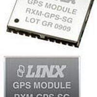
RXM-GPS-SG-T Linx Technologies Inc, RXM-GPS-SG-T Datasheet - Page 12

RXM-GPS-SG-T
Manufacturer Part Number
RXM-GPS-SG-T
Description
GPS MODULE SMD SIRF
Manufacturer
Linx Technologies Inc
Series
SGr
Type
GPS Moduler
Datasheet
1.MDEV-GPS-SG.pdf
(17 pages)
Specifications of RXM-GPS-SG-T
Package / Case
Module
Operating Voltage
4.2 V
Operating Current
46 mA
Frequency Range
1575.42 MHz
Interface Type
UART, USB
Operating Temperature Range
- 30 C to + 85 C
Lead Free Status / RoHS Status
Lead free / RoHS Compliant
Features
-
Voltage - Supply
-
Frequency
-
Operating Temperature
-
Applications
-
Sensitivity
-
Memory Size
-
Data Interface
-
Data Rate - Maximum
-
Modulation Or Protocol
-
Antenna Connector
-
Current - Receiving
-
Lead Free Status / Rohs Status
Lead free / RoHS Compliant
Table 23: Power Management Response Example
Table 24: StaticNavigation Example
Table 25: StaticNavigation Response Example
Page 22
MID
Valid
Mode
OnTime
LP Interval
MaxAcqTime
MaxOffTime
Checksum
<CR> <LF>
MID
Command
Checksum
<CR> <LF>
MID
Valid
Result
Checksum
<CR> <LF>
n Query the power management mode
202 – StaticNavigation
The receiver outputs a response to this command. The table below contains the
response for the above command:
For some further examples of this command:
Input command: $PLSC,200,0*0E
Output response: $PLSR,200,1,1*03
This command is used to query, enable, and disable static navigation. The table
below contains the values for the following example to disable static navigation:
The table below contains the response for the above command:
Name
Name
Name
$PLSR,200
1
2
300
1000
300000
30000
*02
$PLSR,202
1
*02
$PLSR,202
1
2
*1E
Example
Example
Example
$PLSR,200,1,2,300,1000,300000,30000*02
$PLSC,202,2*0E
Units
Units
Units
Message ID
0: command invalid, 1: command valid
See Table 22
Display when mode = 2
Display when mode = 2
Display when mode = 2
Display when mode = 2
End of message termination
Message ID
0: Query, 1: Enable (default), 2: Disable
End of message termination
Message ID
0: command invalid, 1: command valid
0: command failed, 1: static navigation
enabled, 2: static navigation disabled
End of message termination
Description
Description
Description
Table 26: SetIO Example
Table 27: SetIO Response Example
NOTE
1. If the message ID is not recognized, the response will be “$PLSR,999,0,ERROR*60”
2. If the value is not allowed, the response will be “$PLSR,MID,0,ERROR*CS”
3. All GPIOs default to inputs on power-up and reset.
MID
GPIO
Number
Direction
State
Checksum
<CR> <LF>
MID
Valid
Checksum
<CR> <LF>
211 – SetIO
n Set GPIO 1 as an Input
n Set GPIO 1 as an output, initial state low
The table below contains the values for the following example to set GPIO 1 as
an input:
The receiver outputs a response to this command. The table below contains the
response for the above command:
For some further examples of this command:
Input command: $PLSC,211,1,0,0*0F
Output response: $PLSR,211,1*1E
Input command: $PLSC,211,1,1,0*0E
Output response: $PLSR,211,1*1E
Name
Name
1
0
0
*0F
$PLSC,211
Example
$PLSR,211
1
*1E
Example
Units
$PLSC,211,1,0,0*0F
Units
Message ID
Number of the GPIO line to set. Only one
line can be set at a time.
Direction; 0 = Input; 1 = Output
Set to 1 if the direction is an output; the
value does not matter if the direction is an
input.
End of message termination
Message ID
0: command invalid, 1: command valid
End of message termination
Description
Description
Page 23


