RXM-GPS-SR-T Linx Technologies Inc, RXM-GPS-SR-T Datasheet
RXM-GPS-SR-T
Specifications of RXM-GPS-SR-T


Related parts for RXM-GPS-SR-T


RXM-GPS-SR-T Summary of contents
Page 1
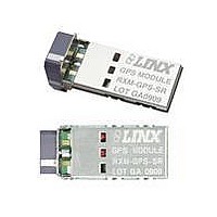
... Reels are 250 pcs. Quantities less than 250 pcs. are supplied in bulk 0.165±0.006 0.992 (4.20±0.15) (25.20) GPS MODULE 0.469 0.402 0.488 (11.90) (10.20) (12.40) RXM-GPS-SR LOT GAxxxx 0.087±0.006 0.402 (2.20±0.15) (10.20) 0.071 (1.80) 0.909 0.047 (23.10) (1.20) Figure 1: Package Dimensions ...
Page 2
ELECTRICAL SPECIFICATIONS Parameter Designation Min. POWER SUPPLY Supply Voltage V 3.0 CC Supply Current Peak – Sleep – Backup Battery Voltage V 1.3 BAT Backup Battery Current I – BAT Output Logic Low Voltage V – OL Output ...
Page 3
A BRIEF OVERVIEW OF GPS The Global Positioning System (GPS U.S.-owned utility that freely and continuously provides positioning, navigation, and timing (PNT) information. Originally created by the U.S. Department of Defense for military applications, the system was made ...
Page 4
POWER CONTROL By default, the SR Series will operate in full power mode. However, it also has a built-in power control mode called Adaptive Trickle Power mode. In this mode, the receiver will power on at full power to acquire ...
Page 5
PROTOCOLS LINX GPS modules use the SiRFstar III chipset. This chipset allows two protocols to be used, NMEA-0183 and SiRF Binary. Switching between the two is handled using a single serial command. The NMEA protocol uses ASCII characters for the ...
Page 6
GLL – Geographic Position – Latitude / Longitude The table below contains the values for the following example: $GPGLL,2503.6319,N,12136.0099,E,053740.000,A,A*52 Name Example Units Message ID $GPGLL GLL protocol header Latitude 2503.6319 ddmm.mmmm N/S indicator N N=north or S=south Longitude 12136.0099 dddmm.mmmm ...
Page 7
RMC – Recommended Minimum Specific GNSS Data The table below contains the values for the following example: $GPRMC,053740.000,A,2503.6319,N,12136.0099,E,2.69,79.65,100106,,,A*53 Name Example Units Message ID $GPRMC RMC protocol header UTC Time 53740 hhmmss.sss Status A A=data valid or V=data not valid Latitude ...
Page 8
SetSerialPort This command message is used to set the protocol (SiRF binary or NMEA) and/or the communication parameters (baud rate). Generally, this command is used to switch the module back to SiRF binary protocol mode where a more ...
Page 9
Query/Rate Control This command is used to control the output of standard NMEA messages GGA, GLL, GSA, GSV, RMC, and VTG. Using this command message, standard NMEA messages may be polled once, or setup for periodic output. Checksums ...
Page 10
Development Data On/Off Use this command to enable development data information if you are having trouble getting commands accepted. Invalid commands generate debug information that enables you to determine the source of the command rejection. Common reasons for ...
Page 11
The receiver outputs a response to this command. The table below contains the response for the above command: $PLSR,200,1,2,300,1000,300000,30000*02 Name Example Units MID $PLSR,200 Message ID Valid 1 0: command invalid, 1: command valid Mode 2 See Table 22 OnTime ...
Page 12
BOARD LAYOUT GUIDELINES The module’s design makes integration straightforward; however still critical to exercise care in PCB layout. Failure to observe good layout techniques can result in degradation of the module’s performance. Grounding, filtering, decoupling, routing and layer ...
Page 13
PAD LAYOUT The following pad layout diagram is designed to facilitate both hand and automated assembly. 0.197 0.094 0.039 0.014 (5.00) (2.40) (1.00) (0.35) 0.118 0.039 D0.031x4 (3.00) (1.00) (0.80) 0.071 (1.80) R0.020x2 0.348 (0.50) (8.85) 0.075 (1.90) 0.055 (1.40) ...
Page 14
ONLINE RESOURCES ® www.linxtechnologies.com • Latest News • Data Guides • Application Notes • Knowledgebase • Software Updates If you have questions regarding any Linx product and have Internet access, make www.linxtechnologies.com your first stop. Our website is organized in ...
Page 15
WIRELESS MADE SIMPLE U.S. CORPORATE HEADQUARTERS LINX TECHNOLOGIES, INC. 159 ORT LANE MERLIN, OR 97532 PHONE: (541) 471-6256 FAX: (541) 471-6251 www.linxtechnologies.com Disclaimer Linx Technologies is continually striving to improve the quality and function of its products. For this ...