RXM-GPS-SG-T Linx Technologies Inc, RXM-GPS-SG-T Datasheet
RXM-GPS-SG-T
Specifications of RXM-GPS-SG-T


Related parts for RXM-GPS-SG-T


RXM-GPS-SG-T Summary of contents
Page 1
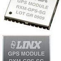
... Tape and Reel, “B” for Bulk n Fleet Management Reels are 1,000 pcs. Quantities less than 1,000 pcs. are supplied in bulk 0.591 (15.00) GPS MODULE 0.512 (13.00) RXM-GPS-SG LOT GRxxxx 0.087 (2.20) Figure 1: Package Dimensions DESCRIPTION GPS Receiver Module Master Development System Revised 1/10/11 ...
Page 2
ELECTRICAL SPECIFICATIONS Parameter Designation Min. POWER SUPPLY Supply Voltage V 3.0 CC Supply Current Peak – Acquisition – Tracking – Standby – Backup Battery Voltage V 1.3 BAT Backup Battery Current I – BAT 2.85V Output Voltage V ...
Page 3
PIN ASSIGNMENTS 1 NC GND 2 NC RFIN 3 1PPS GND 4 TXA VOUT 5 RXA 21 GND GND 6 GPIO10 GPIO13 7 LCKIND GPIO15 8 GPIO1 GPIO14 9 RFPWRUP VCC 10 ON_OFF VBACKUP Figure 2: SG Series Receiver Pinout ...
Page 4
MODULE DESCRIPTION By default, the SG Series will operate in full power mode. However, it also has a built-in power control mode called Adaptive Trickle Power mode. The module is based on the SiRFstar III low power chipset, which consumes ...
Page 5
POWER CONTROL The SG Series has a built-in power control mode called Adaptive Trickle Power mode. In this mode, the receiver will power on at full power to acquire and track satellites and obtain satellite data. It then powers off ...
Page 6
PROTOCOLS LINX GPS modules use the SiRFstar III chipset. This chipset allows two protocols to be used, NMEA-0183 and SiRF Binary. Switching between the two is handled using a single serial command. The NMEA protocol uses ASCII characters for the ...
Page 7
GLL – Geographic Position – Latitude / Longitude The table below contains the values for the following example: $GPGLL,2503.6319,N,12136.0099,E,053740.000,A,A*52 Name Example Units Message ID $GPGLL GLL protocol header Latitude 2503.6319 ddmm.mmmm N/S indicator N N=north or S=south Longitude 12136.0099 dddmm.mmmm ...
Page 8
RMC – Recommended Minimum Specific GNSS Data The table below contains the values for the following example: $GPRMC,053740.000,A,2503.6319,N,12136.0099,E,2.69,79.65,100106,,,A*53 Name Example Units Message ID $GPRMC RMC protocol header UTC Time 53740 hhmmss.sss Status A A=data valid or V=data not valid Latitude ...
Page 9
SetSerialPort This command message is used to set the protocol (SiRF binary or NMEA) and/or the communication parameters (baud rate). Generally, this command is used to switch the module back to SiRF binary protocol mode where a more ...
Page 10
Query/Rate Control This command is used to control the output of standard NMEA messages GGA, GLL, GSA, GSV, RMC, and VTG. Using this command message, standard NMEA messages may be polled once, or setup for periodic output. Checksums ...
Page 11
Development Data On/Off Use this command to enable development data information if you are having trouble getting commands accepted. Invalid commands generate debug information that enables you to determine the source of the command rejection. Common reasons for ...
Page 12
The receiver outputs a response to this command. The table below contains the response for the above command: $PLSR,200,1,2,300,1000,300000,30000*02 Name Example Units MID $PLSR,200 Message ID Valid 1 0: command invalid, 1: command valid Mode 2 See Table 22 OnTime ...
Page 13
ReadInput The table below contains the values for the following example to read the state of an input: $PLSC,212,1*0C Name Example Units MID $PLSC,212 Message ID GPIO Number of the GPIO line to read. Only 1 Number one ...
Page 14
Query The table below contains the values for the following example to read the configuration and state of all of the GPIO lines: $PLSC,215*16 Name Example Units MID $PLSC,215 Message ID Checksum *16 <CR> <LF> End of message ...
Page 15
BOARD LAYOUT GUIDELINES The module’s design makes integration straightforward; however still critical to exercise care in PCB layout. Failure to observe good layout techniques can result in a significant degradation of the module’s performance. A primary layout goal ...
Page 16
PAD LAYOUT The following pad layout diagram is designed to facilitate both hand and automated assembly. 0.020 (0.50) 0.512 (13.00) 0.036 0.050 0.050 (0.92) (1.27) (1.27) Figure 9: Recommended PCB Layout PRODUCTION GUIDELINES The modules are housed in a hybrid ...
Page 17
WIRELESS MADE SIMPLE U.S. CORPORATE HEADQUARTERS LINX TECHNOLOGIES, INC. 159 ORT LANE MERLIN, OR 97532 PHONE: (541) 471-6256 FAX: (541) 471-6251 www.linxtechnologies.com Disclaimer Linx Technologies is continually striving to improve the quality and function of its products. For this ...