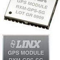
RXM-GPS-SG-T Linx Technologies Inc, RXM-GPS-SG-T Datasheet - Page 11

RXM-GPS-SG-T
Manufacturer Part Number
RXM-GPS-SG-T
Description
GPS MODULE SMD SIRF
Manufacturer
Linx Technologies Inc
Series
SGr
Type
GPS Moduler
Datasheet
1.MDEV-GPS-SG.pdf
(17 pages)
Specifications of RXM-GPS-SG-T
Package / Case
Module
Operating Voltage
4.2 V
Operating Current
46 mA
Frequency Range
1575.42 MHz
Interface Type
UART, USB
Operating Temperature Range
- 30 C to + 85 C
Lead Free Status / RoHS Status
Lead free / RoHS Compliant
Features
-
Voltage - Supply
-
Frequency
-
Operating Temperature
-
Applications
-
Sensitivity
-
Memory Size
-
Data Interface
-
Data Rate - Maximum
-
Modulation Or Protocol
-
Antenna Connector
-
Current - Receiving
-
Lead Free Status / Rohs Status
Lead free / RoHS Compliant
Table 20: Development Data On/Off Example
1. Default setting is debug mode off.
Page 20
Message ID
Debug
Checksum
<CR><LF>
105 – Development Data On/Off
Use this command to enable development data information if you are having
trouble getting commands accepted. Invalid commands generate debug
information that enables you to determine the source of the command rejection.
Common reasons for input command rejection are invalid checksum or
parameter out of specified range.
The table below contains the values for the following example:
1. Debug On
2. Debug Off
Name
$PSRF105
1
*3E
Example
Units
$PSRF105,1*3E
$PSRF105,0*3F
PSRF105 protocol header
0=Off, 1=On
End of message termination
1
Description
Table 21: Power Management Command Example
The table below lists the possible values for the Mode section of this command.
Table 22: Mode Values
Total ON time = OnTime + 160mS + time to process each active NMEA message at
the programmed baud rate (default 9600)
1. Default setting is full power; trickle power disabled.
MID
Mode
OnTime
LP Interval
MaxAcqTime
MaxOffTime
Checksum
<CR> <LF>
200 – PowerManagement
The table below contains the values for the following example to set the receiver
to Adaptive Trickle Power mode:
Name
Value
0
1
2
2
300
(200 - 900)
1000
(1000 -
10000)
300000
(1000 -
2147483000)
30000
(1000 -
1800000)
*0E
Description
Ask receiver to send current power mode
Set receiver to Full power mode
Set receiver to Adaptive Trickle Power mode
$PLSC,200
Example
$PLSC,200,2,300,1000,300000,30000*0E
mS
mS
mS
mS
Units
Message ID
See Table 22
Must be > 200mS and a multiple of 100 (if
not, it is rounded up to the nearest multiple
of 100).
Must be an integer value > 1000 and <10000.
When Adaptive Trickle Power is enabled,
this is the maximum allowable time from
the start of a power cycle to the time a
valid position fix is obtained. If no fix is
obtained in this time, the receiver is
deactivated for up to MaxOffTime, and a
hot start is commanded when the receiver
reactivates. The integer must be in
multiples of 1000mS.
The longest period (in mS) for which the
receiver deactivates due to the
MaxAcqTime timeout. The actual
deactivated period may be less if the user-
specified duty cycle (OnTime / LpInterval)
can be maintained.
End of message termination
1
Description
Page 21


