HSP50216KIZ Intersil, HSP50216KIZ Datasheet - Page 58
HSP50216KIZ
Manufacturer Part Number
HSP50216KIZ
Description
IC DOWNCONVERTER DGTL 4CH 196BGA
Manufacturer
Intersil
Datasheet
1.HSP50216KIZ.pdf
(58 pages)
Specifications of HSP50216KIZ
Function
Downconverter
Rf Type
W-CDMA
Package / Case
196-BGA
Lead Free Status / RoHS Status
Lead free / RoHS Compliant


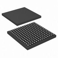
Plastic Ball Grid Array Packages (BGA)
o
Intersil products are sold by description only. Intersil Corporation reserves the right to make changes in circuit design, software and/or specifications at any time without
notice. Accordingly, the reader is cautioned to verify that data sheets are current before placing orders. Information furnished by Intersil is believed to be accurate and
reliable. However, no responsibility is assumed by Intersil or its subsidiaries for its use; nor for any infringements of patents or other rights of third parties which may result
from its use. No license is granted by implication or otherwise under any patent or patent rights of Intersil or its subsidiaries.
A1 CORNER I.D.
A1 CORNER
0.006
0.003
0.15
0.08
A
C
S
M
M
b
A
C
C
All Intersil U.S. products are manufactured, assembled and tested utilizing ISO9000 quality systems.
A B
A1
A2
Intersil Corporation’s quality certifications can be viewed at www.intersil.com/design/quality
14
13
For information regarding Intersil Corporation and its products, see www.intersil.com
12 11 10 9
BOTTOM VIEW
S
58
SIDE VIEW
TOP VIEW
A
8
D1
D
7 6 5
4
3
SEATING PLANE
ALL ROWS AND COLUMNS
2
1
A
e
E
A
B
C
D
E
F
G
H
J
K
L
M
N
P
B
E1
bbb
A1
CORNER
A1
CORNER I.D.
aaa
HSP50216
C
C
V196.12x12
196 BALL PLASTIC BALL GRID ARRAY PACKAGE
NOTES:
SYMBOL
1. Controlling dimension: MILLIMETER. Converted inch
2. Dimensioning and tolerancing conform to ASME Y14.5M-1994.
3. “MD” and “ME” are the maximum ball matrix size for the “D”
4. “N” is the maximum number of balls for the specific array size.
5. Primary datum C and seating plane are defined by the spher-
6. Dimension “A” includes standoff height “A1”, package body
7. Dimension “b” is measured at the maximum ball diameter,
8. Pin “A1” is marked on the top and bottom sides adjacent to A1.
9. “S” is measured with respect to datum’s A and B and defines
MD/ME
D1/E1
D/E
bbb
aaa
A1
A2
dimensions are not necessarily exact.
and “E” dimensions, respectively.
ical crowns of the contact balls.
thickness and lid or cap height “A2”.
parallel to the primary datum C.
the position of the solder balls nearest to package center-
lines. When there is an even number of balls in the outer row
the value is “S” = e/2.
N
A
b
e
0.012
0.037
0.016
0.468
0.405
MIN
-
0.032 BSC
INCHES
14 x 14
0.004
0.005
196
0.016
0.044
0.020
0.413
MAX
0.059
0.476
11.90
10.30
0.31
0.93
0.41
MILLIMETERS
MIN
-
0.80 BSC
14 x 14
0.10
0.12
196
12.10
10.50
MAX
1.50
0.41
1.11
0.51
August 17, 2007
Rev. 2 12/00
NOTES
FN4557.6
7
3
-
-
-
-
-
-
-
-
-
Related parts for HSP50216KIZ
Image
Part Number
Description
Manufacturer
Datasheet
Request
R

Part Number:
Description:
Intersil Corporation [CMOS Serial Controller Interface]
Manufacturer:
Intersil Corporation
Datasheet:
Part Number:
Description:
Manufacturer:
Intersil Corporation
Datasheet:
Part Number:
Description:
357-036-542-201 CARDEDGE 36POS DL .156 BLK LOPRO
Manufacturer:
Intersil Corporation
Datasheet:
Part Number:
Description:
1024-Word x 4-Bit LSI Static RAM
Manufacturer:
Intersil Corporation
Datasheet:
Part Number:
Description:
General Purpose NPN Transistor Arrays FN341.4
Manufacturer:
Intersil Corporation
Datasheet:
Part Number:
Description:
CMOS 16-Bit Microprocessor
Manufacturer:
Intersil Corporation
Datasheet:
Part Number:
Description:
Manufacturer:
Intersil Corporation
Datasheet:
Part Number:
Description:
Manufacturer:
Intersil Corporation
Datasheet:
Part Number:
Description:
Manufacturer:
Intersil Corporation
Datasheet:
Part Number:
Description:
Manufacturer:
Intersil Corporation
Datasheet:
Part Number:
Description:
CMOS 6-Bit Latch and Decoder Memory Interfaces
Manufacturer:
Intersil Corporation
Datasheet:
Part Number:
Description:
CA3046General Purpose NPN Transistor Arrays
Manufacturer:
Intersil Corporation
Datasheet:
Part Number:
Description:
Manufacturer:
Intersil Corporation
Datasheet:
Part Number:
Description:
TR909 DLC/FLC SLIC with Low Power Standby
Manufacturer:
Intersil Corporation
Datasheet:
Part Number:
Description:
Manufacturer:
Intersil Corporation
Datasheet: