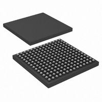
HSP50216KIZ Intersil, HSP50216KIZ Datasheet - Page 33

HSP50216KIZ
Manufacturer Part Number
HSP50216KIZ
Description
IC DOWNCONVERTER DGTL 4CH 196BGA
Manufacturer
Intersil
Datasheet
1.HSP50216KIZ.pdf
(58 pages)
Specifications of HSP50216KIZ
Function
Downconverter
Rf Type
W-CDMA
Package / Case
196-BGA
Lead Free Status / RoHS Status
Lead free / RoHS Compliant
P(15:0)
P(31:0)
P(15:0)
P(15:0)
P(31:0)
31:16
31:19
18:14
15:0
15:0
15:6
13:9
5:1
8:6
2
1
0
0
5
4
3
Enable COF/COFSYNC inputs. When set, this bit enables two bits from the D(15:0) input data bus to be used as a carrier offset
frequency input.
Enable SOF/SOFSYNC inputs. When set, this bit enables two bits from the D(15:0) input data bus to be used as a resampler offset
frequency input.
Enable PN. When set, A PN code, weighted by the gain in location *001, is added to the input samples at the output of the mixer.
Reserved, set to all 0’s.
PN generator gain register. This input is provided to reduce the sensitivity of the receiver. A PN code, weighted by the value in this
location, is added to the data at the output of the mixer. Adding noise has the effect of increasing the receiver noise figure. One reason
to do this would be to decrease the basestation cell size in small steps. This method is very accurate and repeatable and can be
done on a FDM channel by channel basis. It does, however, reduce the overall dynamic range. An alternate way is to add attenuation
at the RF and adjust the whole range upward. This does not reduce the overall range but only shift it, with the shift being done on all
channels simultaneously.
Load with the desired CIC decimation factor minus 1.
CIC output destination (FIR # in FIR processor). Usually set to 00001.
CIC output enable. Active high. When low, the data writes from the CIC to the filter compute engine are inhibited.
Reserved, set to zero.
CIC barrel shift control.
00000 is the minimum shift factor and 11111 is maximum shift factor. This compensates for the CIC filter gain of R
number of enabled CIC stages and R is the CIC decimation factor. The equation used to compute the shift factor is:
Shift Factor = 45 - Ceiling(log
Examples:
N
5
5
CIC stage bypasses. The integrator/comb pairs are numbered 1 through 5 with 1 being the first integrator and first comb. Bit 13
bypasses the first integrator/comb pair, bit 12 bypasses the second, etc. The first integrator is the largest. Typically, the stages are
enabled starting with stage 1 for maximum decimation range.
Carrier phase shift. Phase shifts of N*(π/4), N = 0 to 7.
Clear feedback (test signal or for mixer bypass).
NCO clear feedback on load.
Update frequency on SYNCI. Redundant. Set to1. See Table 37, “RESET/SYNC/INTERRUPT SOURCE SELECTION REGISTER
(GWA = F802h),” on page 43.
TABLE 6. CIC DESTINATION FIR AND OUTPUT ENABLE/DISABLE REGISTER (IWA = *003h)
R
512
8
TABLE 3. CHANNEL INPUT SELECT/FORMAT REGISTER (IWA = *000h) (Continued)
33
Shift Factor
0
30
TABLE 7. CARRIER NCO/CIC CONTROL REGISTER (IWA = *004h)
TABLE 5. CIC DECIMATION FACTOR REGISTER (IWA = *002h)
2
(R
N
)).
TABLE 4. PN GAIN REGISTER (IWA = *001h)
HSP50216
Set to zero.
FUNCTION
FUNCTION
FUNCTION
FUNCTION
FUNCTION
N
, where N is the
August 17, 2007
FN4557.6


