STEVAL-PCC012V1 STMicroelectronics, STEVAL-PCC012V1 Datasheet - Page 98
STEVAL-PCC012V1
Manufacturer Part Number
STEVAL-PCC012V1
Description
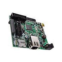
BOARD DEM CONN GATEWAY STM32F107
Manufacturer
STMicroelectronics
Series
STM32r
Type
Other Power Managementr
Datasheets
1.STM32F105V8T6.pdf
(101 pages)
2.STEVAL-PCC012V1.pdf
(10 pages)
3.EVALST7590-1.pdf
(43 pages)
Specifications of STEVAL-PCC012V1
Main Purpose
Interface, Connectivity
Embedded
Yes, MCU, 32-Bit
Utilized Ic / Part
STM32F107
Primary Attributes
Ethernet and 4 Digital/Analog Connectors
Secondary Attributes
On-Board LEDs and Joystick
Interface Type
Ethernet, USB, I2C, SPI, UART
Operating Supply Voltage
3.3 V
Product
Power Management Development Tools
Lead Free Status / RoHS Status
Lead free / RoHS Compliant
For Use With/related Products
STM32F107xx
Other names
497-10757
Available stocks
Company
Part Number
Manufacturer
Quantity
Price
Company:

Part Number:
STEVAL-PCC012V1
Manufacturer:
STMicroelectronics
Quantity:
1


Revision history
98/101
Table 64.
19-Jun-2009
Date
Document revision history (continued)
Revision
3
Section 2.3.8: Boot modes
interface with dedicated DMA and IEEE 1588 support
Section 2.3.24: Remap capability
Figure 1: STM32F105xx and STM32F107xx connectivity line block
diagram
In
– I2S3_WS, I2S3_CK and I2S3_SD default alternate functions
– small changes in signal names
–
– ETH_MII_PPS_OUT and ETH_RMII_PPS_OUT replaced by
– ETH_MII_MDIO and ETH_RMII_MDIO replaced by ETH_MDIO
– ETH_MII_MDC and ETH_RMII_MDC replaced by ETH_MDC
Figures:
(at 3.6 V) - code with data processing running from RAM, peripherals
enabled
frequency (at 3.6 V) - code with data processing running from RAM,
peripherals disabled
Table 13: Maximum current consumption in Run mode, code with
data processing running from
consumption in Run mode, code with data processing running from
RAM
code running from Flash or RAM
Figure 12
I
maximum current consumptions in Stop and Standby
Figure 11: Typical current consumption in Stop mode with regulator
in Run mode versus temperature at different VDD
Typical current consumption in Standby mode versus temperature at
different VDD values
Standby mode versus temperature at different VDD values
Table 17: Typical current consumption in Run mode, code with data
processing running from
consumption in Sleep mode, code running from Flash or RAM
Table 19: Peripheral current consumption
f
characteristics.
Min PLL input clock (f
modified in
ACC
characteristics.
characteristics
Modified:
Figure 29: I2S master timing diagram (Philips protocol)(1)
Figure 31: Ethernet SMI timing
BGA100 package removed.
Section 6.2: Thermal characteristics
DD
HSE_ext
Doc ID 15274 Rev 5
added
Note 6
ETH_PPS_OUT
Table 5: Pin
supply current in Stop mode modified in
HSI
and
max values modified in
modified in
and
and
Typical current consumption in Run mode versus frequency
modified
Figure 28: I2S slave timing diagram (Philips
Table 15: Maximum current consumption in Sleep mode,
and
Table 27: PLL
Typical current consumption in Run mode versus
Figure 5: Memory map
Figure 13
definitions:
updated.
Table 31: EMS characteristics
Table 20: High-speed external user clock
removed.
and
PLL_IN
Table 42: SPI characteristics
show typical curves. PLL1 renamed to PLL.
Figure 13: Typical current consumption in
Flash,
characteristics.
and
), f
Changes
PLL_OUT
Flash,
diagram.
Section 2.3.20: Ethernet MAC
Table 24: HSI oscillator
Table 18: Typical current
are to be determined.
added.
STM32F105xx, STM32F107xx
updated.
added. Small text changes.
Table 14: Maximum current
min and f
updated.
Table 16: Typical and
and
PLL_VCO
values,
Table 32: EMI
modes.
updated.
protocol)(1),
updated.
min
Figure 13:
and
updated.
and
Related parts for STEVAL-PCC012V1
Image
Part Number
Description
Manufacturer
Datasheet
Request
R

Part Number:
Description:
Interface Development Tools Opto ISO USB Bridge 8-Pin Motor CTRL BRD
Manufacturer:
STMicroelectronics
Datasheet:

Part Number:
Description:
BOARD EVAL FOR MEMS SENSORS
Manufacturer:
STMicroelectronics
Datasheet:
Part Number:
Description:
EVALBOARD/STEVAL-ISV014V1
Manufacturer:
STMicroelectronics
Part Number:
Description:
BOARD EVAL FOR ST802RT1
Manufacturer:
STMicroelectronics
Datasheet:

Part Number:
Description:
BOARD EVAL FOR VACUUM CLEANER
Manufacturer:
STMicroelectronics
Datasheet:

Part Number:
Description:
KIT DEV STARTER ST10F276Z5
Manufacturer:
STMicroelectronics
Datasheet:

Part Number:
Description:
BOARD LED CTLR/DVR STLED316S
Manufacturer:
STMicroelectronics
Datasheet:

Part Number:
Description:
BOARD EVAL BLDC SENSORLESS MOTOR
Manufacturer:
STMicroelectronics
Datasheet:

Part Number:
Description:
BOARD ELECT FISCAL CASH REGISTER
Manufacturer:
STMicroelectronics
Datasheet:

Part Number:
Description:
BOARD EVAL BIPO SOLUTION FOR PFC
Manufacturer:
STMicroelectronics
Datasheet:
Part Number:
Description:
STMicroelectronics [RIPPLE-CARRY BINARY COUNTER/DIVIDERS]
Manufacturer:
STMicroelectronics
Datasheet:
Part Number:
Description:
STMicroelectronics [LIQUID-CRYSTAL DISPLAY DRIVERS]
Manufacturer:
STMicroelectronics
Datasheet:
Part Number:
Description:
BOARD EVAL FOR MEMS SENSORS
Manufacturer:
STMicroelectronics
Datasheet: