STEVAL-PCC012V1 STMicroelectronics, STEVAL-PCC012V1 Datasheet - Page 14
STEVAL-PCC012V1
Manufacturer Part Number
STEVAL-PCC012V1
Description
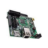
BOARD DEM CONN GATEWAY STM32F107
Manufacturer
STMicroelectronics
Series
STM32r
Type
Other Power Managementr
Datasheets
1.STM32F105V8T6.pdf
(101 pages)
2.STEVAL-PCC012V1.pdf
(10 pages)
3.EVALST7590-1.pdf
(43 pages)
Specifications of STEVAL-PCC012V1
Main Purpose
Interface, Connectivity
Embedded
Yes, MCU, 32-Bit
Utilized Ic / Part
STM32F107
Primary Attributes
Ethernet and 4 Digital/Analog Connectors
Secondary Attributes
On-Board LEDs and Joystick
Interface Type
Ethernet, USB, I2C, SPI, UART
Operating Supply Voltage
3.3 V
Product
Power Management Development Tools
Lead Free Status / RoHS Status
Lead free / RoHS Compliant
For Use With/related Products
STM32F107xx
Other names
497-10757
Available stocks
Company
Part Number
Manufacturer
Quantity
Price
Company:

Part Number:
STEVAL-PCC012V1
Manufacturer:
STMicroelectronics
Quantity:
1


Description
2.3.6
2.3.7
2.3.8
14/101
External interrupt/event controller (EXTI)
The external interrupt/event controller consists of 20 edge detector lines used to generate
interrupt/event requests. Each line can be independently configured to select the trigger
event (rising edge, falling edge, both) and can be masked independently. A pending register
maintains the status of the interrupt requests. The EXTI can detect an external line with a
pulse width shorter than the Internal APB2 clock period. Up to 80 GPIOs can be connected
to the 16 external interrupt lines.
Clocks and startup
System clock selection is performed on startup, however, the internal RC 8 MHz oscillator is
selected as default CPU clock on reset. An external 3-25 MHz clock can be selected, in
which case it is monitored for failure. If failure is detected, the system automatically switches
back to the internal RC oscillator. A software interrupt is generated if enabled. Similarly, full
interrupt management of the PLL clock entry is available when necessary (for example with
failure of an indirectly used external oscillator).
A single 25 MHz crystal can clock the entire system including the ethernet and USB OTG
FS peripherals. Several prescalers and PLLs allow the configuration of the AHB frequency,
the high speed APB (APB2) and the low speed APB (APB1) domains. The maximum
frequency of the AHB and the high speed APB domains is 72 MHz. The maximum allowed
frequency of the low speed APB domain is 36 MHz. Refer to
Ethernet solution on page
The advanced clock controller clocks the core and all peripherals using a single crystal or
oscillator. In order to achieve audio class performance, an audio crystal can be used. In this
case, the I
96 kHz with less than 0.5% accuracy error. Refer to
solution on page
To configure the PLLs, please refer to
configurations according to the application type.
Boot modes
At startup, boot pins are used to select one of three boot options:
●
●
●
The boot loader is located in System Memory. It is used to reprogram the Flash memory by
using USART1, USART2 (remapped), CAN2 (remapped) or USB OTG FS in device mode
(DFU: device firmware upgrade). For remapped signals refer to
The USART peripheral operates with the internal 8 MHz oscillator (HSI), however the CAN
and USB OTG FS can only function if an external 8 MHz, 14.7456 MHz or 25 MHz clock
(HSE) is present.
For full details about the boot loader, please refer to AN2606.
Boot from User Flash
Boot from System Memory
Boot from embedded SRAM
2
S master clock can generate all standard sampling frequencies from 8 kHz to
94.
94.
Doc ID 15274 Rev 5
Table 62 on page
Figure 56: USB OTG FS + I2S (Audio)
95, which provides PLL
STM32F105xx, STM32F107xx
Figure 55: USB OTG FS +
Table 5: Pin
definitions.
Related parts for STEVAL-PCC012V1
Image
Part Number
Description
Manufacturer
Datasheet
Request
R

Part Number:
Description:
Interface Development Tools Opto ISO USB Bridge 8-Pin Motor CTRL BRD
Manufacturer:
STMicroelectronics
Datasheet:

Part Number:
Description:
BOARD EVAL FOR MEMS SENSORS
Manufacturer:
STMicroelectronics
Datasheet:
Part Number:
Description:
EVALBOARD/STEVAL-ISV014V1
Manufacturer:
STMicroelectronics
Part Number:
Description:
BOARD EVAL FOR ST802RT1
Manufacturer:
STMicroelectronics
Datasheet:

Part Number:
Description:
BOARD EVAL FOR VACUUM CLEANER
Manufacturer:
STMicroelectronics
Datasheet:

Part Number:
Description:
KIT DEV STARTER ST10F276Z5
Manufacturer:
STMicroelectronics
Datasheet:

Part Number:
Description:
BOARD LED CTLR/DVR STLED316S
Manufacturer:
STMicroelectronics
Datasheet:

Part Number:
Description:
BOARD EVAL BLDC SENSORLESS MOTOR
Manufacturer:
STMicroelectronics
Datasheet:

Part Number:
Description:
BOARD ELECT FISCAL CASH REGISTER
Manufacturer:
STMicroelectronics
Datasheet:

Part Number:
Description:
BOARD EVAL BIPO SOLUTION FOR PFC
Manufacturer:
STMicroelectronics
Datasheet:
Part Number:
Description:
STMicroelectronics [RIPPLE-CARRY BINARY COUNTER/DIVIDERS]
Manufacturer:
STMicroelectronics
Datasheet:
Part Number:
Description:
STMicroelectronics [LIQUID-CRYSTAL DISPLAY DRIVERS]
Manufacturer:
STMicroelectronics
Datasheet:
Part Number:
Description:
BOARD EVAL FOR MEMS SENSORS
Manufacturer:
STMicroelectronics
Datasheet: