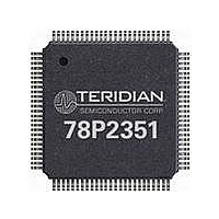
78P2351-IGT/F Maxim Integrated Products, 78P2351-IGT/F Datasheet - Page 7

78P2351-IGT/F
Manufacturer Part Number
78P2351-IGT/F
Description
LINE INTERFACE UNIT 100-LQFP
Manufacturer
Maxim Integrated Products
Specifications of 78P2351-IGT/F
Number Of Channels Per Chip
1
Propagation Delay Time
10 ns
Supply Voltage (max)
3.45 V
Supply Voltage (min)
3.15 V
Maximum Operating Temperature
+ 85 C
Package / Case
LQFP-100
Minimum Operating Temperature
- 40 C
Mounting Style
SMD/SMT
Lead Free Status / RoHS Status
Lead free / RoHS Compliant
Available stocks
Company
Part Number
Manufacturer
Quantity
Price
Company:
Part Number:
78P2351-IGT/F
Manufacturer:
VISHAY
Quantity:
14 105
Company:
Part Number:
78P2351-IGT/F
Manufacturer:
MAXIM
Quantity:
4
Company:
Part Number:
78P2351-IGT/F
Manufacturer:
Maxim Integrated
Quantity:
10 000
Transmit Driver
In CMI (electrical) mode, the CMIP/N pins are biased
and terminated off-chip.
coaxial cable through a 1:1 wideband transformer
and coaxial RF connectors. Reference application
notes for schematic and layout guidelines.
The transmitter encodes the data using CMI line
coding and shapes an analog signal to meet the
appropriate ITU-T G.703 template. The CMI outputs
are tri-stated during transmit disable and transmit
power-down for redundancy applications.
When the CMI pin is low, the chip is in Fiber (NRZ
pass-through) mode and interfaces directly to an
optical transceiver module. The ECLP/N pins are
internally biased and output NRZ data at LVPECL
levels. The CMI driver, encoder and decoder are
disabled in Fiber (NRZ) mode.
Transmit Monitor Mode
An optional redundant transmit output is available in
CMI mode for transmit monitoring. These outputs
(CMI2P/N) are enabled when the RCSL pin or RCSL
register bit is activated.
Clock Synthesizer
The transmit clock synthesizer is a low-jitter DLL that
generates a 278.528/311.04 MHz clock for the CMI
encoder. It is also used in both the receive and
transmit sides for clock and data recovery.
Page: 7 of 42
Note: To avoid reflections causing unwanted
board noise, it’s recommended to power-down
unused transmit ports that are not terminated
with cable to an Rx input port.
Note: This 2x line rate clock is also available at
the
synchronization or system debug.
Figure 6: Transmit Monitor Output
TXCKxP/N
78P2351
TDK
CMI2P/N
CMIP/N
RXP/N
pins
CMI
CMI
CMI
They interface to 75Ω
XFMR
XFMR
XFMR
for
Coax
Coax
Coax
downstream
2006 Teridian Semiconductor Corporation
Transmit Backplane Equalizer
An optional fixed LVPECL equalizer is integrated in
the transmit path for architectures that use LIUs on
active interface cards.
compensate for up to 1.5m of trace and can be
enabled by the TXOUT1 pin or TXEQ bit as follows:
Transmit Loss of Lock
In transmit modes using the integrated CDR, the
78P2351 will declare a loss of lock condition when
there is no valid signal detected at the SIDP/N data
inputs.
POWER-DOWN FUNCTION
Power-down control is provided to allow the
78P2351 to be shut off.
power-down can be set independently through SW
control.
powering down both the transmitter and receiver.
In HW mode, the transmitters can be powered down
using the TXPD control pin.
TXOUT1 pin
Low
Float
Note: The serial interface and configuration
registers are not affected by power-down.
Note: The Tx LOL indicator is invalid and
undefined when the parallel (nibble) interface is
selected.
Global power-down is achieved by
TXEQ bit
OC-3/ STM1-E/ E4 LIU
1
0
The fixed equalizer can
Transmit and receive
Single Channel
Tx Equalizer
78P2351
Disabled
Enabled
Rev. 2.4


