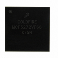
MCF5272VF66 Freescale Semiconductor, MCF5272VF66 Datasheet - Page 6

MCF5272VF66
Manufacturer Part Number
MCF5272VF66
Description
IC MPU 32BIT 66MHZ 196-MAPBGA
Manufacturer
Freescale Semiconductor
Series
MCF527xr
Specifications of MCF5272VF66
Core Processor
Coldfire V2
Core Size
32-Bit
Speed
66MHz
Connectivity
EBI/EMI, Ethernet, I²C, SPI, UART/USART, USB
Peripherals
DMA, WDT
Number Of I /o
32
Program Memory Size
16KB (4K x 32)
Program Memory Type
ROM
Ram Size
1K x 32
Voltage - Supply (vcc/vdd)
3 V ~ 3.6 V
Oscillator Type
External
Operating Temperature
0°C ~ 70°C
Package / Case
196-MAPBGA
Lead Free Status / RoHS Status
Contains lead / RoHS non-compliant
Eeprom Size
-
Data Converters
-
Available stocks
Company
Part Number
Manufacturer
Quantity
Price
Company:
Part Number:
MCF5272VF66
Manufacturer:
HYNIX
Quantity:
19
Company:
Part Number:
MCF5272VF66
Manufacturer:
FREESCAL
Quantity:
885
Company:
Part Number:
MCF5272VF66
Manufacturer:
Freescale Semiconductor
Quantity:
10 000
Part Number:
MCF5272VF66
Manufacturer:
FREESCALE
Quantity:
20 000
Company:
Part Number:
MCF5272VF66J
Manufacturer:
Freescale
Quantity:
256
Company:
Part Number:
MCF5272VF66J
Manufacturer:
Freescale Semiconductor
Quantity:
10 000
Company:
Part Number:
MCF5272VF66R2
Manufacturer:
Freescale Semiconductor
Quantity:
10 000
Company:
Part Number:
MCF5272VF66R2J
Manufacturer:
Freescale Semiconductor
Quantity:
10 000
- Current page: 6 of 544
- Download datasheet (7Mb)
Figure
Number
5-23
5-24
5-25
5-26
5-27
5-28
5-29
5-30
5-31
5-32
5-33
5-34
5-35
5-36
5-37
5-38
5-39
5-40
5-41
6-1
6-2
6-3
6-4
6-5
6-6
6-7
6-8
6-9
6-10
6-11
7-1
7-2
7-3
7-4
7-5
7-6
7-7
7-8
7-9
8-1
8-2
9-1
9-2
9-3
vi
WRITE
WRITE
DUMP
FILL
GO
GO
NOP
NOP
RCREG
RCREG
WCREG
WCREG
RDMREG
WDMREG
WDMREG
Recommended BDM Connector ........................................................................................... 5-41
SIM Block Diagram ................................................................................................................. 6-1
Module Base Address Register (MBAR)................................................................................. 6-4
System Configuration Register (SCR) .................................................................................... 6-5
System Protection Register (SPR).......................................................................................... 6-6
Power Management Register (PMR) ...................................................................................... 6-7
Activate Low-Power Register (ALPR) ................................................................................... 6-10
Device Identification Register (DIR) ...................................................................................... 6-11
Watchdog Reset Reference Register (WRRR) ..................................................................... 6-12
Watchdog Interrupt Reference Register (WIRR)................................................................... 6-12
Watchdog Counter Register (WCR)...................................................................................... 6-13
Watchdog Event Register (WER).......................................................................................... 6-13
Interrupt Controller Block Diagram.......................................................................................... 7-2
Interrupt Control Register 1 (ICR1) ......................................................................................... 7-4
Interrupt Control Register 2 (ICR2) ......................................................................................... 7-5
Interrupt Control Register 3 (ICR3) ......................................................................................... 7-5
Interrupt Control Register 4(ICR4) .......................................................................................... 7-5
Interrupt Source Register (ISR)............................................................................................... 7-6
Programmable Interrupt Transition Register (PITR) ............................................................... 7-7
Programmable Interrupt Wakeup Register (PIWR)................................................................. 7-8
Programmable Interrupt Vector Register (PIVR)..................................................................... 7-9
Chip Select Base Registers (CSBRn) ..................................................................................... 8-3
SDRAM Controller Signals...................................................................................................... 9-2
54-Pin TSOP SDRAM Pin Definition....................................................................................... 9-3
SDRAM Configuration Register (SDCR)................................................................................. 9-6
DUMP
FILL
RDMREG BDM
Chip Select Option Registers (CSORn) ................................................................................. 8-5
Command Format............................................................................................................ 5-29
Command Sequence....................................................................................................... 5-29
Command Sequence...................................................................................................... 5-29
Command Format.......................................................................................................... 5-30
Command Sequence ..................................................................................................... 5-30
Command Format ......................................................................................................... 5-28
Command Sequence................................................................................................... 5-27
Command Format....................................................................................................... 5-25
Command Sequence .................................................................................................. 5-26
Command/Result Formats.......................................................................................... 5-27
Command/Result Formats......................................................................................... 5-30
Command Sequence ................................................................................................. 5-31
Command/Result Formats ........................................................................................ 5-31
Command Sequence ................................................................................................ 5-31
Command Sequence............................................................................................... 5-32
BDM Command Format.......................................................................................... 5-33
Command Sequence .............................................................................................. 5-33
MCF5272 ColdFire
Command/Result Formats .............................................................................. 5-32
List of Figures (Continued)
®
Integrated Microprocessor User’s Manual, Rev. 3
Title
Freescale Semiconductor
Number
Page
Related parts for MCF5272VF66
Image
Part Number
Description
Manufacturer
Datasheet
Request
R
Part Number:
Description:
Mcf5272 Coldfire Integrated Microprocessor User
Manufacturer:
Freescale Semiconductor, Inc
Datasheet:

Part Number:
Description:
MCF5272 Interrupt Service Routine for the Physical Layer Interface Controller
Manufacturer:
Freescale Semiconductor / Motorola
Datasheet:
Part Number:
Description:
Manufacturer:
Freescale Semiconductor, Inc
Datasheet:
Part Number:
Description:
Manufacturer:
Freescale Semiconductor, Inc
Datasheet:
Part Number:
Description:
Manufacturer:
Freescale Semiconductor, Inc
Datasheet:
Part Number:
Description:
Manufacturer:
Freescale Semiconductor, Inc
Datasheet:
Part Number:
Description:
Manufacturer:
Freescale Semiconductor, Inc
Datasheet:
Part Number:
Description:
Manufacturer:
Freescale Semiconductor, Inc
Datasheet:
Part Number:
Description:
Manufacturer:
Freescale Semiconductor, Inc
Datasheet:
Part Number:
Description:
Manufacturer:
Freescale Semiconductor, Inc
Datasheet:
Part Number:
Description:
Manufacturer:
Freescale Semiconductor, Inc
Datasheet:
Part Number:
Description:
Manufacturer:
Freescale Semiconductor, Inc
Datasheet:
Part Number:
Description:
Manufacturer:
Freescale Semiconductor, Inc
Datasheet:
Part Number:
Description:
Manufacturer:
Freescale Semiconductor, Inc
Datasheet:
Part Number:
Description:
Manufacturer:
Freescale Semiconductor, Inc
Datasheet:


