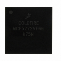
MCF5272VF66 Freescale Semiconductor, MCF5272VF66 Datasheet - Page 28

MCF5272VF66
Manufacturer Part Number
MCF5272VF66
Description
IC MPU 32BIT 66MHZ 196-MAPBGA
Manufacturer
Freescale Semiconductor
Series
MCF527xr
Specifications of MCF5272VF66
Core Processor
Coldfire V2
Core Size
32-Bit
Speed
66MHz
Connectivity
EBI/EMI, Ethernet, I²C, SPI, UART/USART, USB
Peripherals
DMA, WDT
Number Of I /o
32
Program Memory Size
16KB (4K x 32)
Program Memory Type
ROM
Ram Size
1K x 32
Voltage - Supply (vcc/vdd)
3 V ~ 3.6 V
Oscillator Type
External
Operating Temperature
0°C ~ 70°C
Package / Case
196-MAPBGA
Lead Free Status / RoHS Status
Contains lead / RoHS non-compliant
Eeprom Size
-
Data Converters
-
Available stocks
Company
Part Number
Manufacturer
Quantity
Price
Company:
Part Number:
MCF5272VF66
Manufacturer:
HYNIX
Quantity:
19
Company:
Part Number:
MCF5272VF66
Manufacturer:
FREESCAL
Quantity:
885
Company:
Part Number:
MCF5272VF66
Manufacturer:
Freescale Semiconductor
Quantity:
10 000
Part Number:
MCF5272VF66
Manufacturer:
FREESCALE
Quantity:
20 000
Company:
Part Number:
MCF5272VF66J
Manufacturer:
Freescale
Quantity:
256
Company:
Part Number:
MCF5272VF66J
Manufacturer:
Freescale Semiconductor
Quantity:
10 000
Company:
Part Number:
MCF5272VF66R2
Manufacturer:
Freescale Semiconductor
Quantity:
10 000
Company:
Part Number:
MCF5272VF66R2J
Manufacturer:
Freescale Semiconductor
Quantity:
10 000
- Current page: 28 of 544
- Download datasheet (7Mb)
Paragraph
Number
19.17 JTAG Test Access Port and BDM Debug Port ...................................................................... 19-35
19.18 Operating Mode Configuration Pins ...................................................................................... 19-37
19.19 Power Supply Pins ................................................................................................................. 19-38
20.1 Features ...................................................................................................................................... 20-1
20.2 Bus and Control Signals ............................................................................................................ 20-1
20.3 Bus Exception: Double Bus Fault .............................................................................................. 20-3
20.4 Bus Characteristics .................................................................................................................... 20-3
20.5 Data Transfer Mechanism .......................................................................................................... 20-4
20.6 External Bus Interface Types ..................................................................................................... 20-7
20.7 Burst Data Transfers ................................................................................................................ 20-17
20.8 Misaligned Operands ............................................................................................................... 20-18
20.9 Interrupt Cycles ........................................................................................................................ 20-19
20.10 Bus Errors .............................................................................................................................. 20-19
20.11 Bus Arbitration ....................................................................................................................... 20-21
xxviii
19.16.3 GCI/IDL TDM Ports 2 and 3 ...................................................................................... 19-34
19.17.1 Test Clock (TCK/PSTCLK) ........................................................................................ 19-35
19.17.2 Test Mode Select and Force Breakpoint (TMS/BKPT) .............................................. 19-35
19.17.3 Test and Debug Data Out (TDO/DSO) ...................................................................... 19-36
19.17.4 Test and Debug Data In (TDI/DSI) ............................................................................ 19-36
19.17.5 JTAG TRST and BDM Data Clock (TRST/DSCLK) ................................................ 19-36
19.17.6 Freescale Test Mode Select (MTMOD) ..................................................................... 19-36
19.17.7 Debug Transfer Error Acknowledge (TEA) ............................................................... 19-36
19.17.8 Processor Status Outputs (PST[3:0]) .......................................................................... 19-36
19.17.9 Debug Data (DDATA[3:0]) ........................................................................................ 19-37
19.17.10 Device Test Enable (TEST) ...................................................................................... 19-37
20.2.1 Address Bus (A[22:0]) ................................................................................................... 20-2
20.2.2 Data Bus (D[31:0]) ......................................................................................................... 20-2
20.2.3 Read/Write (R/W) ........................................................................................................... 20-2
20.2.4 Transfer Acknowledge (TA) ........................................................................................... 20-2
20.2.5 Transfer Error Acknowledge (TEA) ............................................................................... 20-3
20.5.1 Bus Sizing ....................................................................................................................... 20-4
20.6.1 Interface for FLASH/SRAM Devices with Byte Strobes ............................................... 20-8
20.6.2 Interface for FLASH/SRAM Devices without Byte Strobes ........................................ 20-12
19.16.2.6 D-Channel Grant (DGNT1_INT6/PA15_INT6) ........................................... 19-33
19.16.3.1 GCI/IDL Delayed Frame Sync 2 (DFSC2/PA12) ......................................... 19-34
19.16.3.2 GCI/IDL Delayed Frame Sync 3 (DFSC3/PA13) ......................................... 19-34
19.16.3.3 QSPI_CS3, Port 3 GCI/IDL Data Out 3, PA7 (PA7/DOUT3/QSPI_CS3) ... 19-34
19.16.3.4 INT4 and Port 3 GCI/IDL Data In (INT4/DIN3) ......................................... 19-35
MCF5272 ColdFire
Table of Contents (Continued)
®
Integrated Microprocessor User’s Manual, Rev. 3
Bus Operation
Chapter 20
Title
Freescale Semiconductor
Number
Page
Related parts for MCF5272VF66
Image
Part Number
Description
Manufacturer
Datasheet
Request
R
Part Number:
Description:
Mcf5272 Coldfire Integrated Microprocessor User
Manufacturer:
Freescale Semiconductor, Inc
Datasheet:

Part Number:
Description:
MCF5272 Interrupt Service Routine for the Physical Layer Interface Controller
Manufacturer:
Freescale Semiconductor / Motorola
Datasheet:
Part Number:
Description:
Manufacturer:
Freescale Semiconductor, Inc
Datasheet:
Part Number:
Description:
Manufacturer:
Freescale Semiconductor, Inc
Datasheet:
Part Number:
Description:
Manufacturer:
Freescale Semiconductor, Inc
Datasheet:
Part Number:
Description:
Manufacturer:
Freescale Semiconductor, Inc
Datasheet:
Part Number:
Description:
Manufacturer:
Freescale Semiconductor, Inc
Datasheet:
Part Number:
Description:
Manufacturer:
Freescale Semiconductor, Inc
Datasheet:
Part Number:
Description:
Manufacturer:
Freescale Semiconductor, Inc
Datasheet:
Part Number:
Description:
Manufacturer:
Freescale Semiconductor, Inc
Datasheet:
Part Number:
Description:
Manufacturer:
Freescale Semiconductor, Inc
Datasheet:
Part Number:
Description:
Manufacturer:
Freescale Semiconductor, Inc
Datasheet:
Part Number:
Description:
Manufacturer:
Freescale Semiconductor, Inc
Datasheet:
Part Number:
Description:
Manufacturer:
Freescale Semiconductor, Inc
Datasheet:
Part Number:
Description:
Manufacturer:
Freescale Semiconductor, Inc
Datasheet:


