DLP-USB232R DLP Design Inc, DLP-USB232R Datasheet - Page 4
DLP-USB232R
Manufacturer Part Number
DLP-USB232R
Description
MODULE USB-TO-SRL UART 18-DIP
Manufacturer
DLP Design Inc
Datasheet
1.DLP-USB232R.pdf
(12 pages)
Specifications of DLP-USB232R
Convert From (adapter End)
USB
Convert To (adapter End)
Serial
Interface Type
USB
Product
Interface Modules
For Use With/related Products
Windows® 98 or higher, Mac OS 8.5 or higher
Lead Free Status / RoHS Status
Lead free / RoHS Compliant
Features
-
Lead Free Status / Rohs Status
Lead free / RoHS Compliant
Other names
813-1024


P
P
PINOUT DESCRIPTION
Rev. 1.0 (November 2008)
I
I
10
11
12
13
14
15
16
17
18
N
1
2
3
4
5
6
7
8
9
N
#
#
D
D
GROUND
RTS - Request to Send Control Output/Handshake Signal
RI - Ring Indicator Control Input. When remote wake-up is enabled in the internal
EEPROM taking RI# low (20ms active low pulse), this can be used to resume the PC
USB host controller from Suspend.
DSR - Data Set Ready Control Input/Handshake Signal
CTS - Clear To Send Control Input/Handshake Signal
CBUS4 - Configurable CBUS output-only pin. The function of this pin is configured in the
FT232R internal EEPROM (see CBUS Signal Options in the next section).
VCCIO - +1.8V to +5.25V supply for the UART interface and CBUS group (Pins 6, 11,
12, 14 and 15). Connect this pin to an external power supply to drive out at +3.3V levels
(or another voltage within the specified range), or connect to EXTVCC (Pin 8) to drive out
at the +5V CMOS level.
EXTVCC - Use for applying main power (4.0 to 5.25 volts) to the module. Connect to
PORTVCC (Pin 9) if the module is to be powered by the USB port (typical configuration).
PORTVCC - Power from the USB port. Connect to EXTVCC (Pin 8) if the module is to
be powered by the USB port (typical configuration). 500mA is the maximum current
available to the USB adapter and target electronics if the USB device is configured for
high power.
GROUND
CBUS2 - Configurable CBUS I/O pin. The function of this pin is configured in the
FT232R internal EEPROM (see CBUS Signal Options in the next section).
CBUS3 - Configurable CBUS I/O Pin. The function of this pin is configured in the
FT232R internal EEPROM (see CBUS Signal Options in the next section).
DCD - Data Carrier Detect Control Input
CBUS1 - Configurable CBUS I/O Pin. The function of this pin is configured in the
FT232R internal EEPROM (see CBUS Signal Options in the next section).
CBUS0 - Configurable CBUS I/O Pin. The function of this pin is configured in the
FT232R internal EEPROM (see CBUS Signal Options in the next section).
RXD - Receiving Asynchronous Data Input
DTR - Data Terminal Ready Control Output/Handshake Signal
TXD - Transmit Asynchronous Data Output
E
E
S
S
C
C
R
R
I
I
P
P
T
T
I
I
O
O
N
N
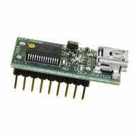
(Interface Headers on bottom of PCB)
Pin 9
Pin 1
Top View
USB
4
Pin 18
Pin 10
© DLP Design, Inc.
Related parts for DLP-USB232R
Image
Part Number
Description
Manufacturer
Datasheet
Request
R

Part Number:
Description:
Interface Modules & Development Tools Dual Ch USB Adapter w/ FTDI FT2232H
Manufacturer:
DLP Design Inc
Datasheet:

Part Number:
Description:
Interface Modules & Development Tools USB to MSP430 w/ FTDI FT2232H
Manufacturer:
DLP Design Inc
Datasheet:

Part Number:
Description:
MODULE USB SECURITY DONGLE
Manufacturer:
DLP Design Inc
Datasheet:

Part Number:
Description:
MODULE USB-TO-UART/FIFO HS 18DIP
Manufacturer:
DLP Design Inc
Datasheet:

Part Number:
Description:
MODULE USB ADAPTER FOR FT2232D
Manufacturer:
DLP Design Inc
Datasheet:

Part Number:
Description:
MODULE USB-TO-FPGA TOOL W/MANUAL
Manufacturer:
DLP Design Inc
Datasheet:
Part Number:
Description:
Interface Modules & Development Tools RETRACTABLE USB CBL USB TO MINI USB
Manufacturer:
DLP Design Inc
Part Number:
Description:
Interface Modules & Development Tools USB FPGA Module w/ Xilinx XC3S400A
Manufacturer:
DLP Design Inc
Datasheet:

Part Number:
Description:
MODULE USB-TO-PARL FIFO 18-DIP
Manufacturer:
DLP Design Inc
Datasheet:

Part Number:
Description:
MODULE USB ADAPTR FOR FT2232D LP
Manufacturer:
DLP Design Inc
Datasheet:

Part Number:
Description:
MODULE USB-MCU FT245RL W/16F877A
Manufacturer:
DLP Design Inc
Datasheet:

Part Number:
Description:
MODULE USB-TO-FPGA TRAINING TOOL
Manufacturer:
DLP Design Inc
Datasheet:

Part Number:
Description:
MODULE USB-MCU FT232R W/18F2410
Manufacturer:
DLP Design Inc
Datasheet:

Part Number:
Description:
MODULE USB-MCU FT245RL W/SX48
Manufacturer:
DLP Design Inc
Datasheet:

Part Number:
Description:
MODULE USB-MCU FT2232D W/16F877A
Manufacturer:
DLP Design Inc
Datasheet: