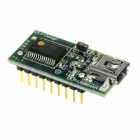
DLP-USB245R DLP Design Inc, DLP-USB245R Datasheet - Page 8

DLP-USB245R
Manufacturer Part Number
DLP-USB245R
Description
MODULE USB-TO-PARL FIFO 18-DIP
Manufacturer
DLP Design Inc
Datasheet
1.DLP-USB245R.pdf
(13 pages)
Specifications of DLP-USB245R
Convert From (adapter End)
USB
Convert To (adapter End)
Parallel
Features
Bi-Directional
Interface Type
USB
Operating Supply Voltage
3.3 V to 5.25 V
Product
Interface Modules
For Use With/related Products
Windows® 98 or higher, Mac OS 8.5 or higher
Lead Free Status / RoHS Status
Lead free / RoHS Compliant
Lead Free Status / RoHS Status
Lead free / RoHS Compliant, Lead free / RoHS Compliant
Other names
813-1025
8.0 DEVICE CONFIGURATION EXAMPLES
USB Bus-Powered and Self-Powered Configurations
Figure 1.
The figure above illustrates a typical USB bus-powered configuration. A USB bus-powered
device gets its power from the USB bus. Basic rules for USB bus-powered devices are as
follows:
1. On plug-in to USB, the module and external circuitry should draw no more than 100mA on
the 5-volt line from the USB host.
2. In USB Suspend Mode, the module and external circuitry should draw no more than 2.5mA.
3. A bus-powered, high-power USB device (one that draws more than 100mA) should use one
of the CBUS pins configured as PWREN# to keep the current below 100mA on plug-in and
below 2.5mA on USB Suspend.
4. A design that consumes more than 100mA in total cannot be plugged into a USB
bus-powered hub.
5. No USB target system can draw more than 500mA from the USB bus. The power descriptors
in the internal EEPROM of the FT245R should be programmed to match the total current drawn
by the target system.
Note: If using PWREN# (available using the CBUS), the I/O pin should be pulled to VCCIO
using a 10k-ohm resistor.
Rev. 1.0 (November 2008)
Bus-Powered
5V System
7
8
9
8
© DLP Design, Inc.


