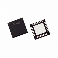
C8051F321 Silicon Laboratories Inc, C8051F321 Datasheet - Page 53

C8051F321
Manufacturer Part Number
C8051F321
Description
IC 8051 MCU 16K FLASH 28MLP
Manufacturer
Silicon Laboratories Inc
Series
C8051F32xr
Datasheet
1.C8051F320R.pdf
(256 pages)
Specifications of C8051F321
Core Processor
8051
Core Size
8-Bit
Speed
25MHz
Connectivity
SMBus (2-Wire/I²C), SPI, UART/USART, USB
Peripherals
Brown-out Detect/Reset, POR, PWM, Temp Sensor, WDT
Number Of I /o
21
Program Memory Size
16KB (16K x 8)
Program Memory Type
FLASH
Ram Size
2.25K x 8
Voltage - Supply (vcc/vdd)
2.7 V ~ 3.6 V
Data Converters
A/D 13x10b
Oscillator Type
Internal
Operating Temperature
-40°C ~ 85°C
Package / Case
28-VQFN Exposed Pad, 28-HVQFN, 28-SQFN, 28-DHVQFN
Lead Free Status / RoHS Status
Contains lead / RoHS non-compliant
Eeprom Size
-
Available stocks
Company
Part Number
Manufacturer
Quantity
Price
Company:
Part Number:
C8051F321
Manufacturer:
SILICON
Quantity:
249
Part Number:
C8051F321
Manufacturer:
SILICON LABS/芯科
Quantity:
20 000
Company:
Part Number:
C8051F321-GM
Manufacturer:
SiliconL
Quantity:
4 364
Part Number:
C8051F321-GM
Manufacturer:
SILICON LABS/芯科
Quantity:
20 000
Part Number:
C8051F321-GMR
Manufacturer:
SILICON LABS/芯科
Quantity:
20 000
5.4.2. Window Detector In Differential Mode
Figure 5.17
ADC0LTH:ADC0LTL = 0x0040 (+64d) and ADC0GTH:ADC0GTH = 0xFFFF (-1d). In differential mode, the mea-
surable voltage between the input pins is between -VREF and VREF*(511/512). Output codes are represented as 10-
bit 2’s complement signed integers. In the left example, an AD0WINT interrupt will be generated if the ADC0 con-
version word (ADC0H:ADC0L) is within the range defined by ADC0GTH:ADC0GTL and ADC0LTH:ADC0LTL
(if 0xFFFF (-1d) < ADC0H:ADC0L < 0x0040 (64d)). In the right example, an AD0WINT interrupt will be generated
if the ADC0 conversion word is outside of the range defined by the ADC0GT and ADC0LT registers
(if ADC0H:ADC0L < 0xFFFF (-1d) or ADC0H:ADC0L > 0x0040 (+64d)). Figure 5.18 shows an example using
left-justified data with equivalent ADC0GT and ADC0LT register settings..
VREF x (511/512)
VREF x (511/512)
VREF x (64/512)
VREF x (64/512)
VREF x (-1/512)
VREF x (-1/512)
Input Voltage
Input Voltage
(Px.x - Px.x)
(Px.x - Px.x)
Figure 5.17. ADC Window Compare Example: Right-Justified Differential Data
Figure 5.18. ADC Window Compare Example: Left-Justified Differential Data
-VREF
-VREF
shows
ADC0H:ADC0L
ADC0H:ADC0L
0xFFFF
0xFFFE
0x7FC0
0x0FC0
0xFFC0
0x01FF
0x0041
0x0040
0x003F
0x0000
0x0200
0x1040
0x1000
0x0000
0xFF80
0x8000
two
example
ADC0GTH:ADC0GTL
ADC0GTH:ADC0GTL
ADC0LTH:ADC0LTL
ADC0LTH:ADC0LTL
not affected
not affected
not affected
not affected
AD0WINT
AD0WINT
AD0WINT
AD0WINT
window
AD0WINT=1
AD0WINT=1
comparisons
Rev. 1.1
VREF x (511/512)
VREF x (511/512)
VREF x (64/512)
VREF x (64/512)
VREF x (-1/512)
VREF x (-1/512)
Input Voltage
Input Voltage
(Px.x - Px.x)
(Px.x - Px.y)
-VREF
-VREF
for
right-justified,
ADC0H:ADC0L
ADC0H:ADC0L
0xFFFF
0xFFFE
0x7FC0
0x0FC0
0xFFC0
0x01FF
0x0041
0x0040
0x003F
0x0000
0x0200
0x1040
0x1000
0x0000
0xFF80
0x8000
C8051F320/1
ADC0GTH:ADC0GTL
ADC0GTH:ADC0GTL
differential
ADC0LTH:ADC0LTL
ADC0LTH:ADC0LTL
not affected
not affected
AD0WINT
AD0WINT
AD0WINT=1
AD0WINT=1
AD0WINT=1
AD0WINT=1
data,
with
53


