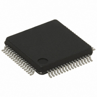
ST7FMC2R7T6TR STMicroelectronics, ST7FMC2R7T6TR Datasheet - Page 274

ST7FMC2R7T6TR
Manufacturer Part Number
ST7FMC2R7T6TR
Description
IC MCU 8BIT 32K FLASH 64-LQFP
Manufacturer
STMicroelectronics
Series
ST7r
Datasheet
1.ST7FMC2S4T6.pdf
(309 pages)
Specifications of ST7FMC2R7T6TR
Core Processor
ST7
Core Size
8-Bit
Speed
8MHz
Connectivity
LINSCI, SPI
Peripherals
LVD, Motor Control PWM, POR, PWM, WDT
Number Of I /o
44
Program Memory Size
48KB (48K x 8)
Program Memory Type
FLASH
Ram Size
1.5K x 8
Voltage - Supply (vcc/vdd)
3.8 V ~ 5.5 V
Data Converters
A/D 16x10b
Oscillator Type
Internal
Operating Temperature
-40°C ~ 85°C
Package / Case
64-LQFP
For Use With
497-8402 - BOARD EVAL COMPLETE INVERTER497-8400 - KIT IGBT PWR MODULE CTRL ST7MC497-6408 - BOARD EVAL BLDC SENSORLESS MOTOR497-4734 - EVAL KIT 3KW POWER DRIVER BOARD497-4733 - EVAL KIT 1KW POWER DRIVER BOARD497-4732 - EVAL KIT 300W POWER DRIVER BOARD497-4731 - EVAL KIT PWR DRIVER CONTROL BRD
Lead Free Status / RoHS Status
Lead free / RoHS Compliant
Eeprom Size
-
Available stocks
Company
Part Number
Manufacturer
Quantity
Price
Company:
Part Number:
ST7FMC2R7T6TR
Manufacturer:
STMicroelectronics
Quantity:
10 000
- Current page: 274 of 309
- Download datasheet (6Mb)
ST7MC1xx/ST7MC2xx
MOTOR CONTROL CHARACTERISTICS (Cont’d)
12.12.2 Input Stage (comparator + sampling)
Note:
1. The comparator accuracy is dependent of the environment. The offset value is given for a comparison done with all
digital I/Os stable. Negative injection current on the I/Os close to the inputs may reduce the accuracy. In particular care
must be taken to avoid switching on I/Os close to the inputs when the comparator is in use. This phenomenon is even
more critical when a big external serial resistor is added on the inputs.
2. This filter is implemented to wait for comparator stabilization and avoid any wrong information during start-up.
3. This delay represents the number of clock cycles needed to generate an event as soon as the comparator output
or MCO outputs change.
Example: In tachogenerator mode, this means that capture is performed on the 4th clock cycle after comparator commu-
tation., i.e. there is a variation of (1/f
274/309
Symbol
t
sampling
t
t
V
I
propag
startup
offset
V
offset
IN
Comparator input volt-
age range
Comparator offset error
Input offset current
Comparator propagation
delay
Start-up filter duration
Digital sampling delay
Parameter
2)
3)
mtc
Time waited before sampling when com-
parator is turned ON, i.e. CKE=1 or
DAC=1 (with f
Time needed to generate a capture in
tachogenerator mode as soon as the MCI
input toggles
Time needed to capture MTIM in MZREG
(BEMF) when sampling during PWM sig-
nal OFF time as soon as MCO becomes
ON
Time needed to set/reset the HST bit
when sampling during PWM signal OFF
time as soon as MCO becomes ON
(BEMF)
Time needed to generate Z event (MTIM
captured in MZREG) as soon as the com-
parator toggles (when sampling at f
Time needed to generate D event (MTIM
captured in MDREG) as soon as the com-
parator toggles
Time needed to set/reset the HST bit
when sampling during PWM signal ON
time after a delay (DS>0) as soon as
MCO becomes ON
Time needed to generate Z event (MTIM
in MZREG) when sampling during PWM
signal ON time after a delay (DS>0) as
soon as MCO becomes ON
Time needed to generate Z event (MTIM
captured in MZREG) when sampling dur-
ing PWM signal ON time at f
delay (DS>0)
) or (1 / f
SCF
) depending on the case.
PERIPH
Conditions
= 4MHz)
SCF
after a
SCF
)
V
SSA
1 / f
1 / f
Min
Delay programmed in DS bits
Delay programmed in DS bits
Delay programmed in DS bits
- 0.1
SCF
SCF
3 / f
1 / f
(MCONF) +1 / f
+ 1 / f
+ 3 / f
+ 3 / f
(see
(see
(see
mtc
mtc
Typ
(MCONF)
(MCONF)
(see
(see
+ 3 / f
3
35
Figure
SCF
4 / f
5
mtc
mtc
Figure
Figure
Figure
(see
(see
mtc
Figure
+ 3 / f
mtc
V
152)
152)
152)
DD
Max
40
Figure
Figure
100
mtc
mtc
+ 0.1
1
150)
150)
1)
151)
151)
Unit
mV
μA
ns
μs
V
Related parts for ST7FMC2R7T6TR
Image
Part Number
Description
Manufacturer
Datasheet
Request
R

Part Number:
Description:
STMicroelectronics [RIPPLE-CARRY BINARY COUNTER/DIVIDERS]
Manufacturer:
STMicroelectronics
Datasheet:

Part Number:
Description:
STMicroelectronics [LIQUID-CRYSTAL DISPLAY DRIVERS]
Manufacturer:
STMicroelectronics
Datasheet:

Part Number:
Description:
BOARD EVAL FOR MEMS SENSORS
Manufacturer:
STMicroelectronics
Datasheet:

Part Number:
Description:
NPN TRANSISTOR POWER MODULE
Manufacturer:
STMicroelectronics
Datasheet:

Part Number:
Description:
TURBOSWITCH ULTRA-FAST HIGH VOLTAGE DIODE
Manufacturer:
STMicroelectronics
Datasheet:

Part Number:
Description:
Manufacturer:
STMicroelectronics
Datasheet:

Part Number:
Description:
DIODE / SCR MODULE
Manufacturer:
STMicroelectronics
Datasheet:

Part Number:
Description:
DIODE / SCR MODULE
Manufacturer:
STMicroelectronics
Datasheet:

Part Number:
Description:
Search -----> STE16N100
Manufacturer:
STMicroelectronics
Datasheet:

Part Number:
Description:
Search ---> STE53NA50
Manufacturer:
STMicroelectronics
Datasheet:

Part Number:
Description:
NPN Transistor Power Module
Manufacturer:
STMicroelectronics
Datasheet:

Part Number:
Description:
DIODE / SCR MODULE
Manufacturer:
STMicroelectronics
Datasheet:


