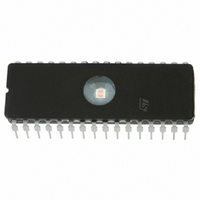
ST7FMC1K2B6 STMicroelectronics, ST7FMC1K2B6 Datasheet - Page 205

ST7FMC1K2B6
Manufacturer Part Number
ST7FMC1K2B6
Description
MCU 8BIT 8K FLASH 32DIP
Manufacturer
STMicroelectronics
Series
ST7r
Datasheet
1.ST7FMC2S4T6.pdf
(309 pages)
Specifications of ST7FMC1K2B6
Core Processor
ST7
Core Size
8-Bit
Speed
8MHz
Connectivity
LINSCI
Peripherals
LVD, Motor Control PWM, POR, PWM, WDT
Number Of I /o
17
Program Memory Size
8KB (8K x 8)
Program Memory Type
FLASH
Ram Size
384 x 8
Voltage - Supply (vcc/vdd)
3.8 V ~ 5.5 V
Data Converters
A/D 16x10b
Oscillator Type
Internal
Operating Temperature
-40°C ~ 85°C
Package / Case
32-DIP (0.600", 15.24mm)
For Use With
497-8402 - BOARD EVAL COMPLETE INVERTER497-8400 - KIT IGBT PWR MODULE CTRL ST7MC497-4734 - EVAL KIT 3KW POWER DRIVER BOARD497-4733 - EVAL KIT 1KW POWER DRIVER BOARD497-4732 - EVAL KIT 300W POWER DRIVER BOARD497-4731 - EVAL KIT PWR DRIVER CONTROL BRD
Lead Free Status / RoHS Status
Lead free / RoHS Compliant
Eeprom Size
-
Other names
497-4864
- Current page: 205 of 309
- Download datasheet (6Mb)
MOTOR CONTROLLER (Cont’d)
10.6.10.5 Repetition Down-Counter
Both in center-aligned and edge-aligned modes,
the four Compare registers (one Compare 0 and
three for the U, V and W phases) are updated
when the PWM counter underflow or overflow and
the 8-bit Repetition down-counter has reached ze-
ro.
This means that data are transferred from the
preload compare registers to the compare regis-
ters every N cycles of the PWM Counter, where N
is the value of the 8-bit Repetition register in edge
-aligned mode. When using center-aligned mode,
the repetition down-counter is decremented every
time the PWM counter overflows or underflows. Al-
though this limits the maximum number of repeti-
tion to 128 PWM cycles, this makes it possible to
update the duty cycle twice per PWM period. As a
result, the effective PWM resolution in that case is
equal to the resolution we can get using edge-
Figure 122. Update rate examples depending on mode and MREP register settings
re-synchronization
MREP = 0
MREP = 1
MREP = 2
MREP = 3
MREP = 3
12-bit PWM
and
Counter
U
U Event: Preload registers transferred to active registers and PWM interrupt generated
U Event if transition from MREP = 0 to MREP = 1 occurs when 12-bit counter is equal
U
U
U
U
U
(by SW)
Center-aligned mode
to MCP0.
aligned mode, i.e. one T
ing compare registers only once per PWM period
in center-aligned mode, maximum resolution is
2xT
The repetition down counter is an auto-reload
type; the repetition rate will be maintained as de-
fined by the MREP register value (refer to
122).
10.6.10.6 PWM interrupt generation
A PWM interrupt is generated synchronously with
the “U” update event, which allows to refresh com-
pare values by software before the next update
event. As a result, the refresh rate for phases duty
cycles is directly linked to MREP register setting.
A signal reflecting the update events may be out-
put on a standard I/O port for debugging purposes.
Refer to
tails.
mtc
, due to the symmetry of the pattern.
section10.6.7.3 on page 172
(by SW)
Edge-aligned mode
ST7MC1xx/ST7MC2xx
mtc
period. When refresh-
for more de-
205/309
Figure
1
Related parts for ST7FMC1K2B6
Image
Part Number
Description
Manufacturer
Datasheet
Request
R

Part Number:
Description:
STMicroelectronics [RIPPLE-CARRY BINARY COUNTER/DIVIDERS]
Manufacturer:
STMicroelectronics
Datasheet:

Part Number:
Description:
STMicroelectronics [LIQUID-CRYSTAL DISPLAY DRIVERS]
Manufacturer:
STMicroelectronics
Datasheet:

Part Number:
Description:
BOARD EVAL FOR MEMS SENSORS
Manufacturer:
STMicroelectronics
Datasheet:

Part Number:
Description:
NPN TRANSISTOR POWER MODULE
Manufacturer:
STMicroelectronics
Datasheet:

Part Number:
Description:
TURBOSWITCH ULTRA-FAST HIGH VOLTAGE DIODE
Manufacturer:
STMicroelectronics
Datasheet:

Part Number:
Description:
Manufacturer:
STMicroelectronics
Datasheet:

Part Number:
Description:
DIODE / SCR MODULE
Manufacturer:
STMicroelectronics
Datasheet:

Part Number:
Description:
DIODE / SCR MODULE
Manufacturer:
STMicroelectronics
Datasheet:

Part Number:
Description:
Search -----> STE16N100
Manufacturer:
STMicroelectronics
Datasheet:

Part Number:
Description:
Search ---> STE53NA50
Manufacturer:
STMicroelectronics
Datasheet:

Part Number:
Description:
NPN Transistor Power Module
Manufacturer:
STMicroelectronics
Datasheet:

Part Number:
Description:
DIODE / SCR MODULE
Manufacturer:
STMicroelectronics
Datasheet:


