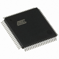
AT80C51SND1C-ROTIL Atmel, AT80C51SND1C-ROTIL Datasheet - Page 117

AT80C51SND1C-ROTIL
Manufacturer Part Number
AT80C51SND1C-ROTIL
Description
IC MCU FLASH MP3 DECODER 80-TQFP
Manufacturer
Atmel
Series
80Cr
Datasheet
1.AT80C51SND1C-ROTIL.pdf
(213 pages)
Specifications of AT80C51SND1C-ROTIL
Core Processor
8051
Core Size
8-Bit
Speed
40MHz
Connectivity
I²C, IDE/ATAPI, MMC, SPI, UART/USART, USB
Peripherals
Audio, I²S, MP3, PCM, POR, WDT
Number Of I /o
44
Program Memory Type
ROMless
Ram Size
2.25K x 8
Voltage - Supply (vcc/vdd)
2.7 V ~ 3.3 V
Data Converters
A/D 2x10b
Oscillator Type
Internal
Operating Temperature
-40°C ~ 85°C
Package / Case
80-TQFP, 80-VQFP
Lead Free Status / RoHS Status
Contains lead / RoHS non-compliant
Eeprom Size
-
Program Memory Size
-
Other names
AT80C51SND1CROTIL
Available stocks
Company
Part Number
Manufacturer
Quantity
Price
- Current page: 117 of 213
- Download datasheet (3Mb)
16.5.2
16.6
4109L–8051–02/08
Data Line Controller
Command Receiver
•
Figure 16-14 summarizes the command transmission flow.
As soon as command transmission is enabled, the CFLCK flag in MMSTA is set indicating that
write to the FIFO is locked. This mechanism is implemented to avoid command overrun.
The end of the command transmission is signalled to you by the EOCI flag in MMINT register
becoming set. This flag may generate an MMC interrupt request as detailed in Section "Inter-
rupt", page 123. The end of the command transmission also resets the CFLCK flag.
User may abort command loading by setting and clearing the CTPTR bit in MMCON0 register
which resets the write pointer to the transmit FIFO.
Figure 16-14. Command Transmission Flow
The end of the response reception is signalled to you by the EORI flag in MMINT register. This
flag may generate an MMC interrupt request as detailed in Section "Interrupt", page 123. When
this flag is set, 2 other flags in MMSTA register: RESPFS and CRC7S give a status on the
response received. RESPFS indicates if the response format is correct or not: the size is the one
expected (48 bits or 136 bits) and a valid End bit has been received, and CRC7S indicates if the
CRC7 computation is correct or not. These Flags are cleared when a command is sent to the
card and updated when the response has been received.
User may abort response reading by setting and clearing the CRPTR bit in MMCON0 register
which resets the read pointer to the receive FIFO.
According to the MMC specification delay between a command and a response (formally N
parameter) can not exceed 64 MMC clock periods. To avoid any locking of the MMC controller
when card does not send its response (e.g. physically removed from the bus), user must launch
a time-out period to exit from such situation. In case of time-out user may reset the command
controller and its internal state machine by setting and clearing the CCR bit in MMCON2
register.
This time-out may be disarmed when receiving the response.
The data line controller is based on a 16-Byte FIFO used both by the data transmitter channel
and by the data receiver channel.
CRCDIS bit in MMCON0 register to indicate whether the CRC7 included in the response will
be computed or not. In order to avoid CRC error, CRCDIS may be set for response that do
not include CRC7.
Configure Response
Transmission
RESPEN = X
Command
CRCDIS = X
RFMT = X
Transmit Command
MMCMD = argument
Load Command in
MMCMD = index
CMDEN = 1
CMDEN = 0
Buffer
AT8xC51SND1C
117
CR
Related parts for AT80C51SND1C-ROTIL
Image
Part Number
Description
Manufacturer
Datasheet
Request
R

Part Number:
Description:
DEV KIT FOR AVR/AVR32
Manufacturer:
Atmel
Datasheet:

Part Number:
Description:
INTERVAL AND WIPE/WASH WIPER CONTROL IC WITH DELAY
Manufacturer:
ATMEL Corporation
Datasheet:

Part Number:
Description:
Low-Voltage Voice-Switched IC for Hands-Free Operation
Manufacturer:
ATMEL Corporation
Datasheet:

Part Number:
Description:
MONOLITHIC INTEGRATED FEATUREPHONE CIRCUIT
Manufacturer:
ATMEL Corporation
Datasheet:

Part Number:
Description:
AM-FM Receiver IC U4255BM-M
Manufacturer:
ATMEL Corporation
Datasheet:

Part Number:
Description:
Monolithic Integrated Feature Phone Circuit
Manufacturer:
ATMEL Corporation
Datasheet:

Part Number:
Description:
Multistandard Video-IF and Quasi Parallel Sound Processing
Manufacturer:
ATMEL Corporation
Datasheet:

Part Number:
Description:
High-performance EE PLD
Manufacturer:
ATMEL Corporation
Datasheet:

Part Number:
Description:
8-bit Flash Microcontroller
Manufacturer:
ATMEL Corporation
Datasheet:

Part Number:
Description:
2-Wire Serial EEPROM
Manufacturer:
ATMEL Corporation
Datasheet:


