HD6473308RCP10V Renesas Electronics America, HD6473308RCP10V Datasheet - Page 74
HD6473308RCP10V
Manufacturer Part Number
HD6473308RCP10V
Description
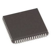
MCU 5V 16K,PB-FREE 80-PLCC
Manufacturer
Renesas Electronics America
Series
H8® H8/330r
Datasheet
1.HD6473258P10V.pdf
(349 pages)
Specifications of HD6473308RCP10V
Core Size
8-Bit
Program Memory Size
16KB (16K x 8)
Oscillator Type
Internal
Core Processor
H8/300
Speed
10MHz
Number Of I /o
58
Program Memory Type
OTP
Ram Size
512 x 8
Operating Temperature
-20°C ~ 75°C
Package / Case
80-PLCC
No. Of I/o's
58
Ram Memory Size
512Byte
Cpu Speed
10MHz
No. Of Timers
3
No. Of Pwm Channels
2
Digital Ic Case
RoHS Compliant
Controller Family/series
H8/330
Peripherals
ADC
Rohs Compliant
Yes
Lead Free Status / RoHS Status
Lead free / RoHS Compliant
Voltage - Supply (vcc/vdd)
-
Eeprom Size
-
Data Converters
-
Peripherals
-
Connectivity
-
Lead Free Status / RoHS Status
Lead free / RoHS Compliant
Available stocks
Company
Part Number
Manufacturer
Quantity
Price
Company:

Part Number:
HD6473308RCP10V
Manufacturer:
Renesas Electronics America
Quantity:
10 000


As indicated in table 4-1, the H8/330 recognizes only two kinds of exceptions: interrupts (28
sources) and the reset. There are no error or trap exceptions.
When an exception occurs the CPU enters the exception-handling state and performs a hardware
exception-handling sequence. There are two exception-handling sequences: one for the reset and
one for interrupts. In both sequences the CPU:
• Sets the interrupt mask (I) bit in the CCR to “1,” and
• Loads the program counter (PC) from the vector table.
After the program counter is loaded, the CPU returns to the program execution state and program
execution starts from the new PC address.
The vector table occupies addresses H’0000 to H’003D in memory. It consists of word entries
giving the addresses of software interrupt-handling routines and the reset routine. The entries are
indexed by a vector number associated with the particular exception.
For an interrupt, before the PC and CCR are altered as described above, the old PC and CCR
contents are pushed on the stack, so that they can be restored when an RTE (Return from
Exception ) instruction is executed.
If a reset and interrupt occur simultaneously, the reset has priority. There is also a priority order
among different types of interrupts. Table 4-1 compares the reset and interrupt exceptions.
Table 4-1. Reset and Interrupt Exceptions
Item
Priority
Cause
When detected
When handled
Vector numbers
Vector table
Reset
Highest
Low RES input
Any clock period
Immediately
0
H’0000 – H’0001
Section 4. Exception Handling
Interrupt
Lower
Internal or external interrupt signal
At end of current instruction, unless current
instruction is ANDC, ORC, XORC, or LDC, or at
end of hardware interrupt-handling sequence.
At end of current instruction.
3 to 30
H’0006 – H’003D
59
Related parts for HD6473308RCP10V
Image
Part Number
Description
Manufacturer
Datasheet
Request
R

Part Number:
Description:
KIT STARTER FOR M16C/29
Manufacturer:
Renesas Electronics America
Datasheet:

Part Number:
Description:
KIT STARTER FOR R8C/2D
Manufacturer:
Renesas Electronics America
Datasheet:

Part Number:
Description:
R0K33062P STARTER KIT
Manufacturer:
Renesas Electronics America
Datasheet:

Part Number:
Description:
KIT STARTER FOR R8C/23 E8A
Manufacturer:
Renesas Electronics America
Datasheet:

Part Number:
Description:
KIT STARTER FOR R8C/25
Manufacturer:
Renesas Electronics America
Datasheet:

Part Number:
Description:
KIT STARTER H8S2456 SHARPE DSPLY
Manufacturer:
Renesas Electronics America
Datasheet:

Part Number:
Description:
KIT STARTER FOR R8C38C
Manufacturer:
Renesas Electronics America
Datasheet:

Part Number:
Description:
KIT STARTER FOR R8C35C
Manufacturer:
Renesas Electronics America
Datasheet:

Part Number:
Description:
KIT STARTER FOR R8CL3AC+LCD APPS
Manufacturer:
Renesas Electronics America
Datasheet:
Part Number:
Description:
KIT STARTER FOR RX610
Manufacturer:
Renesas Electronics America
Datasheet:

Part Number:
Description:
KIT STARTER FOR R32C/118
Manufacturer:
Renesas Electronics America
Datasheet:

Part Number:
Description:
KIT DEV RSK-R8C/26-29
Manufacturer:
Renesas Electronics America
Datasheet:

Part Number:
Description:
KIT STARTER FOR SH7124
Manufacturer:
Renesas Electronics America
Datasheet:

Part Number:
Description:
KIT STARTER FOR H8SX/1622
Manufacturer:
Renesas Electronics America
Datasheet:

Part Number:
Description:
KIT DEV FOR SH7203
Manufacturer:
Renesas Electronics America
Datasheet: