HD6473308RCP10V Renesas Electronics America, HD6473308RCP10V Datasheet - Page 223
HD6473308RCP10V
Manufacturer Part Number
HD6473308RCP10V
Description
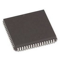
MCU 5V 16K,PB-FREE 80-PLCC
Manufacturer
Renesas Electronics America
Series
H8® H8/330r
Datasheet
1.HD6473258P10V.pdf
(349 pages)
Specifications of HD6473308RCP10V
Core Size
8-Bit
Program Memory Size
16KB (16K x 8)
Oscillator Type
Internal
Core Processor
H8/300
Speed
10MHz
Number Of I /o
58
Program Memory Type
OTP
Ram Size
512 x 8
Operating Temperature
-20°C ~ 75°C
Package / Case
80-PLCC
No. Of I/o's
58
Ram Memory Size
512Byte
Cpu Speed
10MHz
No. Of Timers
3
No. Of Pwm Channels
2
Digital Ic Case
RoHS Compliant
Controller Family/series
H8/330
Peripherals
ADC
Rohs Compliant
Yes
Lead Free Status / RoHS Status
Lead free / RoHS Compliant
Voltage - Supply (vcc/vdd)
-
Eeprom Size
-
Data Converters
-
Peripherals
-
Connectivity
-
Lead Free Status / RoHS Status
Lead free / RoHS Compliant
Available stocks
Company
Part Number
Manufacturer
Quantity
Price
Company:

Part Number:
HD6473308RCP10V
Manufacturer:
Renesas Electronics America
Quantity:
10 000


The ADCSR is initialized to H’00 at a reset and in the standby modes.
Bit 7 – A/D End Flag (ADF): This status flag indicates the end of one cycle of A/D conversion.
Bit 7
ADF
Bit 6 – A/D Interrupt Enable (ADIE): This bit selects whether to request an A/D interrupt (ADI)
when A/D conversion is completed.
Bit 6
ADIE
Bit 5 – A/D Start (ADST): The A/D converter operates while this bit is set to “1.” In the single
mode, this bit is automatically cleared to “0” at the end of each A/D conversion.
Bit 5
ADST
0
1
0
1
0
1
Description
To clear ADF, the CPU must read ADF after
it has been set to "1," then write a "0" in this bit.
This bit is set to 1 at the following times:
(1) Single mode: when one A/D conversion is completed.
(2) Scan mode: when inputs on all selected channels have
Description
The A/D interrupt request (ADI) is disabled.
The A/D interrupt request (ADI) is enabled.
Description
A/D conversion is halted.
(1) Single mode: One A/D conversion is performed. The ADST
(2) Scan mode: A/D conversion starts and continues cyclically on the selected
been converted.
bit is automatically cleared to “0” at the end of the conversion.
channels until the ADST bit is cleared to “0” by software (or a reset, or by entry to
a standby mode).
211
(Initial value)
(Initial value)
(Initial value)
Related parts for HD6473308RCP10V
Image
Part Number
Description
Manufacturer
Datasheet
Request
R

Part Number:
Description:
KIT STARTER FOR M16C/29
Manufacturer:
Renesas Electronics America
Datasheet:

Part Number:
Description:
KIT STARTER FOR R8C/2D
Manufacturer:
Renesas Electronics America
Datasheet:

Part Number:
Description:
R0K33062P STARTER KIT
Manufacturer:
Renesas Electronics America
Datasheet:

Part Number:
Description:
KIT STARTER FOR R8C/23 E8A
Manufacturer:
Renesas Electronics America
Datasheet:

Part Number:
Description:
KIT STARTER FOR R8C/25
Manufacturer:
Renesas Electronics America
Datasheet:

Part Number:
Description:
KIT STARTER H8S2456 SHARPE DSPLY
Manufacturer:
Renesas Electronics America
Datasheet:

Part Number:
Description:
KIT STARTER FOR R8C38C
Manufacturer:
Renesas Electronics America
Datasheet:

Part Number:
Description:
KIT STARTER FOR R8C35C
Manufacturer:
Renesas Electronics America
Datasheet:

Part Number:
Description:
KIT STARTER FOR R8CL3AC+LCD APPS
Manufacturer:
Renesas Electronics America
Datasheet:
Part Number:
Description:
KIT STARTER FOR RX610
Manufacturer:
Renesas Electronics America
Datasheet:

Part Number:
Description:
KIT STARTER FOR R32C/118
Manufacturer:
Renesas Electronics America
Datasheet:

Part Number:
Description:
KIT DEV RSK-R8C/26-29
Manufacturer:
Renesas Electronics America
Datasheet:

Part Number:
Description:
KIT STARTER FOR SH7124
Manufacturer:
Renesas Electronics America
Datasheet:

Part Number:
Description:
KIT STARTER FOR H8SX/1622
Manufacturer:
Renesas Electronics America
Datasheet:

Part Number:
Description:
KIT DEV FOR SH7203
Manufacturer:
Renesas Electronics America
Datasheet: