MC908MR32CFUE Freescale Semiconductor, MC908MR32CFUE Datasheet - Page 63
MC908MR32CFUE
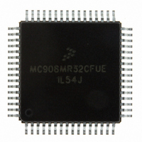
Manufacturer Part Number
MC908MR32CFUE
Description
IC MCU 8MHZ 32K FLASH 64-QFP
Manufacturer
Freescale Semiconductor
Series
HC08r
Datasheet
1.MC908MR16CFUE.pdf
(282 pages)
Specifications of MC908MR32CFUE
Core Processor
HC08
Core Size
8-Bit
Speed
8MHz
Connectivity
SCI, SPI
Peripherals
LVD, POR, PWM
Number Of I /o
44
Program Memory Size
32KB (32K x 8)
Program Memory Type
FLASH
Ram Size
768 x 8
Voltage - Supply (vcc/vdd)
4.5 V ~ 5.5 V
Data Converters
A/D 10x10b
Oscillator Type
Internal
Operating Temperature
-40°C ~ 85°C
Package / Case
64-QFP
Processor Series
HC08MR
Core
HC08
Data Bus Width
8 bit
Data Ram Size
768 B
Interface Type
SCI/SPI
Maximum Clock Frequency
8.2 MHz
Number Of Programmable I/os
44
Number Of Timers
6
Operating Supply Voltage
0 V to 5 V
Maximum Operating Temperature
+ 85 C
Mounting Style
SMD/SMT
Development Tools By Supplier
FSICEBASE, M68CBL05CE
Minimum Operating Temperature
- 40 C
On-chip Adc
10-ch x 10-bit
Lead Free Status / RoHS Status
Lead free / RoHS Compliant
Eeprom Size
-
Lead Free Status / Rohs Status
Lead free / RoHS Compliant
Available stocks
Company
Part Number
Manufacturer
Quantity
Price

Company:
Part Number:
MC908MR32CFUE
Manufacturer:
Freescale Semiconductor
Quantity:
10 000
Part Number:
MC908MR32CFUE
Manufacturer:
NXP/恩智浦
Quantity:
20 000


two to correct the duty cycle. Therefore, the bus clock frequency, which is one-half of the base clock
frequency, is one-fourth the frequency of the selected clock (CGMXCLK or CGMVCLK).
The BCS bit in the PLL control register (PCTL) selects which clock drives CGMOUT. The VCO clock
cannot be selected as the base clock source if the PLL is not turned on. The PLL cannot be turned off if
the VCO clock is selected. The PLL cannot be turned on or off simultaneously with the selection or
deselection of the VCO clock. The VCO clock also cannot be selected as the base clock source if the
factor L is programmed to a 0. This value would set up a condition inconsistent with the operation of the
PLL, so that the PLL would be disabled and the crystal clock would be forced as the source of the base
clock.
4.3.4 CGM External Connections
In its typical configuration, the CGM requires seven external components. Five of these are for the crystal
oscillator and two are for the PLL.
The crystal oscillator is normally connected in a Pierce oscillator configuration, as shown in
Figure 4-3
circuitry.
The oscillator configuration uses five components:
The series resistor (R
be required for all ranges of operation, especially with high-frequency crystals. Refer to the crystal
manufacturer’s data for more information.
Freescale Semiconductor
1. Crystal, X
2. Fixed capacitor, C
3. Tuning capacitor, C
4. Feedback resistor, R
5. Series resistor, R
shows only the logical representation of the internal components and may not represent actual
1
SIMOSCEN
S
) is included in the diagram to follow strict Pierce oscillator guidelines and may not
S
1
OSC1
C1
(optional)
2
MC68HC908MR32 • MC68HC908MR16 Data Sheet, Rev. 6.1
B
(can also be a fixed capacitor)
R
X1
Figure 4-3. CGM External Connections
B
OSC2
R
C2
S
*
CGMXCLK
V
SS
*RS can be 0 (shorted) when used with
higher frequency crystals. Refer to
manufacturer’s data.
CGMXFC
C
F
V
C
DDA
BYP
Functional Description
V
DD
Figure
4-3.
63
Related parts for MC908MR32CFUE
Image
Part Number
Description
Manufacturer
Datasheet
Request
R

Part Number:
Description:
Manufacturer:
Freescale Semiconductor, Inc
Datasheet:
Part Number:
Description:
Manufacturer:
Freescale Semiconductor, Inc
Datasheet:
Part Number:
Description:
Manufacturer:
Freescale Semiconductor, Inc
Datasheet:
Part Number:
Description:
Manufacturer:
Freescale Semiconductor, Inc
Datasheet:
Part Number:
Description:
Manufacturer:
Freescale Semiconductor, Inc
Datasheet:
Part Number:
Description:
Manufacturer:
Freescale Semiconductor, Inc
Datasheet:
Part Number:
Description:
Manufacturer:
Freescale Semiconductor, Inc
Datasheet:
Part Number:
Description:
Manufacturer:
Freescale Semiconductor, Inc
Datasheet:
Part Number:
Description:
Manufacturer:
Freescale Semiconductor, Inc
Datasheet:
Part Number:
Description:
Manufacturer:
Freescale Semiconductor, Inc
Datasheet:
Part Number:
Description:
Manufacturer:
Freescale Semiconductor, Inc
Datasheet:
Part Number:
Description:
Manufacturer:
Freescale Semiconductor, Inc
Datasheet:
Part Number:
Description:
Manufacturer:
Freescale Semiconductor, Inc
Datasheet:
Part Number:
Description:
Manufacturer:
Freescale Semiconductor, Inc
Datasheet:
Part Number:
Description:
Manufacturer:
Freescale Semiconductor, Inc
Datasheet: