MC9S12C128CPBE Freescale Semiconductor, MC9S12C128CPBE Datasheet - Page 664
MC9S12C128CPBE
Manufacturer Part Number
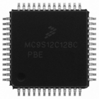
MC9S12C128CPBE
Description
IC MCU 128K FLASH 25MHZ 52-LQFP
Manufacturer
Freescale Semiconductor
Series
HCS12r
Specifications of MC9S12C128CPBE
Core Processor
HCS12
Core Size
16-Bit
Speed
25MHz
Connectivity
CAN, EBI/EMI, SCI, SPI
Peripherals
POR, PWM, WDT
Number Of I /o
35
Program Memory Size
128KB (128K x 8)
Program Memory Type
FLASH
Ram Size
4K x 8
Voltage - Supply (vcc/vdd)
2.35 V ~ 5.5 V
Data Converters
A/D 8x10b
Oscillator Type
Internal
Operating Temperature
-40°C ~ 85°C
Package / Case
52-LQFP
Lead Free Status / RoHS Status
Lead free / RoHS Compliant
Eeprom Size
-
Available stocks
Company
Part Number
Manufacturer
Quantity
Price

Company:
Part Number:
MC9S12C128CPBE
Manufacturer:
Freescale Semiconductor
Quantity:
10 000
Company:
Part Number:
MC9S12C128CPBER
Manufacturer:
Freescale Semiconductor
Quantity:
10 000


Appendix A Electrical Characteristics
A.4.1.3
Provided an appropriate external reset signal is applied to the MCU, preventing the CPU from executing
code when V
the PORF bit in the CRG Flags Register has not been set.
A.4.1.4
When external reset is asserted for a time greater than PW
reset, and the CPU starts fetching the reset vector without doing a clock quality check, if there was an
oscillation before reset.
A.4.1.5
Out of STOP the controller can be woken up by an external interrupt. A clock quality check as after POR
is performed before releasing the clocks to the system.
A.4.1.6
The recovery from Pseudo STOP and Wait are essentially the same since the oscillator was not stopped in
both modes. In Pseudo Stop Mode the voltage regulator is switched to reduced performance mode to
reduce power consumption. The returning out of pseudo stop to full performance takes t
can be woken up by internal or external interrupts.After t
starts fetching the interrupt vector.
A.4.2
The device features an internal Colpitts and Pierce oscillator. The selection of Colpitts oscillator or Pierce
oscillator/external clock depends on the XCLKS signal which is sampled during reset. Pierce
oscillator/external clock mode allows the input of a square wave. Before asserting the oscillator to the
internal system clocks the quality of the oscillation is checked for each start from either power-on, STOP
or oscillator fail. t
POR or STOP if a proper oscillation is not detected. The quality check also determines the minimum
oscillator start-up time t
asserted if the frequency of the incoming clock signal is below the Assert Frequency f
664
Oscillator
DD5
SRAM Data Retention
External Reset
Stop Recovery
Pseudo Stop and Wait Recovery
is out of specification limits, the SRAM contents integrity is guaranteed if after the reset
CQOUT
UPOSC
specifies the maximum time before switching to the internal self clock mode after
. The device also features a clock monitor. A Clock Monitor Failure is
MC9S12C-Family / MC9S12GC-Family
Rev 01.24
wrs
RSTL
in Wait or t
the CRG module generates an internal
vup
+ t
wrs
in Pseudo Stop the CPU
Freescale Semiconductor
CMFA.
vup
. The controller
Related parts for MC9S12C128CPBE
Image
Part Number
Description
Manufacturer
Datasheet
Request
R

Part Number:
Description:
Manufacturer:
Freescale Semiconductor, Inc
Datasheet:
Part Number:
Description:
Manufacturer:
Freescale Semiconductor, Inc
Datasheet:
Part Number:
Description:
Manufacturer:
Freescale Semiconductor, Inc
Datasheet:
Part Number:
Description:
Manufacturer:
Freescale Semiconductor, Inc
Datasheet:
Part Number:
Description:
Manufacturer:
Freescale Semiconductor, Inc
Datasheet:
Part Number:
Description:
Manufacturer:
Freescale Semiconductor, Inc
Datasheet:
Part Number:
Description:
Manufacturer:
Freescale Semiconductor, Inc
Datasheet:
Part Number:
Description:
Manufacturer:
Freescale Semiconductor, Inc
Datasheet:
Part Number:
Description:
Manufacturer:
Freescale Semiconductor, Inc
Datasheet:
Part Number:
Description:
Manufacturer:
Freescale Semiconductor, Inc
Datasheet:
Part Number:
Description:
Manufacturer:
Freescale Semiconductor, Inc
Datasheet:
Part Number:
Description:
Manufacturer:
Freescale Semiconductor, Inc
Datasheet:
Part Number:
Description:
Manufacturer:
Freescale Semiconductor, Inc
Datasheet:
Part Number:
Description:
Manufacturer:
Freescale Semiconductor, Inc
Datasheet:
Part Number:
Description:
Manufacturer:
Freescale Semiconductor, Inc
Datasheet: