MC9S12C128CPBE Freescale Semiconductor, MC9S12C128CPBE Datasheet - Page 659
MC9S12C128CPBE
Manufacturer Part Number
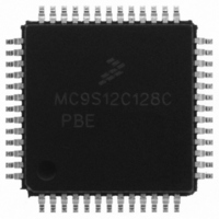
MC9S12C128CPBE
Description
IC MCU 128K FLASH 25MHZ 52-LQFP
Manufacturer
Freescale Semiconductor
Series
HCS12r
Specifications of MC9S12C128CPBE
Core Processor
HCS12
Core Size
16-Bit
Speed
25MHz
Connectivity
CAN, EBI/EMI, SCI, SPI
Peripherals
POR, PWM, WDT
Number Of I /o
35
Program Memory Size
128KB (128K x 8)
Program Memory Type
FLASH
Ram Size
4K x 8
Voltage - Supply (vcc/vdd)
2.35 V ~ 5.5 V
Data Converters
A/D 8x10b
Oscillator Type
Internal
Operating Temperature
-40°C ~ 85°C
Package / Case
52-LQFP
Lead Free Status / RoHS Status
Lead free / RoHS Compliant
Eeprom Size
-
Available stocks
Company
Part Number
Manufacturer
Quantity
Price

Company:
Part Number:
MC9S12C128CPBE
Manufacturer:
Freescale Semiconductor
Quantity:
10 000
Company:
Part Number:
MC9S12C128CPBER
Manufacturer:
Freescale Semiconductor
Quantity:
10 000


A.2.2
The
The following constraints exist to obtain full-scale, full range results: V
This constraint exists since the sample buffer amplifier can not drive beyond the power supply levels that
it ties to. If the input level goes outside of this range it will effectively be clipped
1. The minimum time assumes a final sample period of 2 ATD clocks cycles while the maximum time assumes a final sample
A.2.3
Three factors — source resistance, source capacitance and current injection — have an influence on the
accuracy of the ATD.
A.2.3.1
Due to the input pin leakage current as specified in
there will be a voltage drop from the signal source to the ATD input. The maximum source resistance R
specifies results in an error of less than 1/2 LSB (2.5mV) at the maximum leakage current. If device or
operating conditions are less than worst case or leakage-induced error is acceptable, larger values of source
resistance is allowable.
A.2.3.2
When sampling an additional internal capacitor is switched to the input. This can cause a voltage drop due
to charge sharing with the external and the pin capacitance. For a maximum sampling error of the input
voltage ≤ 1LSB, then the external filter capacitor, C
Freescale Semiconductor
Conditions are shown in
Num C
period of 16 ATD clocks.
1
2
3
4
5
6
7
Table A-11
D
C Differential Reference Voltage
D ATD Clock Frequency
D
D
D Recovery Time (V
P Reference Supply current
Reference Potential
ATD 10-Bit Conversion Period
ATD 8-Bit Conversion Period
ATD Operating Characteristics In 3.3V Range
Factors Influencing Accuracy
Source Resistance
Source Capacitance
shows conditions under which the ATD operates.
Conv, Time at 2.0MHz ATD Clock f
Conv, Time at 2.0MHz ATD Clock f
Table A-4
DDA
=3.3 Volts)
Rating
unless otherwise noted; Supply Voltage 3.3V-10% <= V
Table A-11. ATD Operating Characteristics
MC9S12C-Family / MC9S12GC-Family
Clock Cycles
Clock Cycles
ATDCLK
ATDCLK
Rev 01.24
High
Low
(1)
Table A-6
f
1
≥ 1024 * (C
N
V
T
Symbol
N
f
T
ATDCLK
CONV10
RH
CONV10
CONV8
CONV8
t
I
V
V
REC
REF
RH
RL
-V
RL
in conjunction with the source resistance
INS
V
V
DDA
Min
3.0
0.5
14
12
—
—
– C
SSA
7
6
SSA
/2
INN
DDA
Appendix A Electrical Characteristics
≤ V
).
<= 3.3V+10%
RL
Typ
3.3
—
—
—
—
—
—
—
—
—
≤ V
IN
≤ V
V
0.250
V
Max
DDA
3.6
2.0
28
14
26
13
20
DDA
RH
/2
≤ V
Cycles
Cycles
MHz
Unit
DDA
mA
µs
µs
µs
V
V
V
659
S
.
Related parts for MC9S12C128CPBE
Image
Part Number
Description
Manufacturer
Datasheet
Request
R

Part Number:
Description:
Manufacturer:
Freescale Semiconductor, Inc
Datasheet:
Part Number:
Description:
Manufacturer:
Freescale Semiconductor, Inc
Datasheet:
Part Number:
Description:
Manufacturer:
Freescale Semiconductor, Inc
Datasheet:
Part Number:
Description:
Manufacturer:
Freescale Semiconductor, Inc
Datasheet:
Part Number:
Description:
Manufacturer:
Freescale Semiconductor, Inc
Datasheet:
Part Number:
Description:
Manufacturer:
Freescale Semiconductor, Inc
Datasheet:
Part Number:
Description:
Manufacturer:
Freescale Semiconductor, Inc
Datasheet:
Part Number:
Description:
Manufacturer:
Freescale Semiconductor, Inc
Datasheet:
Part Number:
Description:
Manufacturer:
Freescale Semiconductor, Inc
Datasheet:
Part Number:
Description:
Manufacturer:
Freescale Semiconductor, Inc
Datasheet:
Part Number:
Description:
Manufacturer:
Freescale Semiconductor, Inc
Datasheet:
Part Number:
Description:
Manufacturer:
Freescale Semiconductor, Inc
Datasheet:
Part Number:
Description:
Manufacturer:
Freescale Semiconductor, Inc
Datasheet:
Part Number:
Description:
Manufacturer:
Freescale Semiconductor, Inc
Datasheet:
Part Number:
Description:
Manufacturer:
Freescale Semiconductor, Inc
Datasheet: