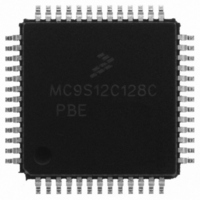
MC9S12C128CPBE Freescale Semiconductor, MC9S12C128CPBE Datasheet - Page 115

MC9S12C128CPBE
Manufacturer Part Number
MC9S12C128CPBE
Description
IC MCU 128K FLASH 25MHZ 52-LQFP
Manufacturer
Freescale Semiconductor
Series
HCS12r
Specifications of MC9S12C128CPBE
Core Processor
HCS12
Core Size
16-Bit
Speed
25MHz
Connectivity
CAN, EBI/EMI, SCI, SPI
Peripherals
POR, PWM, WDT
Number Of I /o
35
Program Memory Size
128KB (128K x 8)
Program Memory Type
FLASH
Ram Size
4K x 8
Voltage - Supply (vcc/vdd)
2.35 V ~ 5.5 V
Data Converters
A/D 8x10b
Oscillator Type
Internal
Operating Temperature
-40°C ~ 85°C
Package / Case
52-LQFP
Lead Free Status / RoHS Status
Lead free / RoHS Compliant
Eeprom Size
-
Available stocks
Company
Part Number
Manufacturer
Quantity
Price
Company:
Part Number:
MC9S12C128CPBE
Manufacturer:
Freescale Semiconductor
Quantity:
10 000
Company:
Part Number:
MC9S12C128CPBER
Manufacturer:
Freescale Semiconductor
Quantity:
10 000
- Current page: 115 of 690
- Download datasheet (4Mb)
3.3.2.3
Read: Anytime
Write: The EEON bit can be written to any time on all devices. Bits E[11:15] are “write anytime in all
modes” on most devices. On some devices, bits E[11:15] are “write once in normal and emulation modes
and write anytime in special modes”. See device overview chapter to determine the actual write access
rights.
This register initializes the position of the internal EEPROM within the on-chip system memory map.
Freescale Semiconductor
Module Base + 0x0012
Starting address location affected by INITRG register setting.
1. The reset state of this register is controlled at chip integration. Please refer to the device overview section to determine the
EE[15:11]
Reset
actual reset state of this register.
EEON
Field
7:3
0
W
R
1
EE15
Internal EEPROM Map Position — These bits determine the upper five bits of the base address for the system’s
internal EEPROM array.
Enable EEPROM — This bit is used to enable the EEPROM memory in the memory map.
0 Disables the EEPROM from the memory map.
1 Enables the EEPROM in the memory map at the address selected by EE[15:11].
Initialization of Internal EEPROM Position Register (INITEE)
—
7
Writes to this register take one cycle to go into effect.
Figure 3-5. Initialization of Internal EEPROM Position Register (INITEE)
= Unimplemented or Reserved
EE14
—
6
Table 3-4. INITEE Field Descriptions
EE13
MC9S12C-Family / MC9S12GC-Family
—
5
EE12
Rev 01.24
NOTE
—
4
Description
Chapter 3 Module Mapping Control (MMCV4) Block Description
EE11
—
3
—
0
2
—
0
1
EEON
—
0
115
Related parts for MC9S12C128CPBE
Image
Part Number
Description
Manufacturer
Datasheet
Request
R
Part Number:
Description:
Manufacturer:
Freescale Semiconductor, Inc
Datasheet:
Part Number:
Description:
Manufacturer:
Freescale Semiconductor, Inc
Datasheet:
Part Number:
Description:
Manufacturer:
Freescale Semiconductor, Inc
Datasheet:
Part Number:
Description:
Manufacturer:
Freescale Semiconductor, Inc
Datasheet:
Part Number:
Description:
Manufacturer:
Freescale Semiconductor, Inc
Datasheet:
Part Number:
Description:
Manufacturer:
Freescale Semiconductor, Inc
Datasheet:
Part Number:
Description:
Manufacturer:
Freescale Semiconductor, Inc
Datasheet:
Part Number:
Description:
Manufacturer:
Freescale Semiconductor, Inc
Datasheet:
Part Number:
Description:
Manufacturer:
Freescale Semiconductor, Inc
Datasheet:
Part Number:
Description:
Manufacturer:
Freescale Semiconductor, Inc
Datasheet:
Part Number:
Description:
Manufacturer:
Freescale Semiconductor, Inc
Datasheet:
Part Number:
Description:
Manufacturer:
Freescale Semiconductor, Inc
Datasheet:
Part Number:
Description:
Manufacturer:
Freescale Semiconductor, Inc
Datasheet:
Part Number:
Description:
Manufacturer:
Freescale Semiconductor, Inc
Datasheet:
Part Number:
Description:
Manufacturer:
Freescale Semiconductor, Inc
Datasheet:


