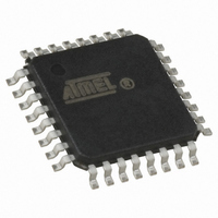
ATMEGA16U2-AUR Atmel, ATMEGA16U2-AUR Datasheet - Page 219

ATMEGA16U2-AUR
Manufacturer Part Number
ATMEGA16U2-AUR
Description
MCU AVR 8K FLASH 16MHZ 32TQFP
Manufacturer
Atmel
Series
AVR® ATmegar
Specifications of ATMEGA16U2-AUR
Core Processor
AVR
Core Size
8-Bit
Speed
16MHz
Connectivity
SPI, UART/USART, USB
Peripherals
Brown-out Detect/Reset, POR, PWM, WDT
Number Of I /o
22
Program Memory Size
16KB (8K x 16)
Program Memory Type
FLASH
Eeprom Size
512 x 8
Ram Size
512 x 8
Voltage - Supply (vcc/vdd)
2.7 V ~ 5.5 V
Oscillator Type
Internal
Operating Temperature
-40°C ~ 85°C
Package / Case
32-TQFP, 32-VQFP
Lead Free Status / RoHS Status
Lead free / RoHS Compliant
Data Converters
-
- Current page: 219 of 309
- Download datasheet (6Mb)
21.18.15 UEINTX – USB Endpoint Interrupt Register
7799D–AVR–11/10
• Bit 7 – FIFOCON: FIFO Control Bit
This bit can only be written to zero by software. Writing this bit to one has no effect. The behav-
ior of this bit depends on the direction of the selected endpoint.
This flag is set by the USB controller when a new OUT message is stored in the current bank. In
this situation RXOUT or RXSTP flags are also updated at the same time. Writing this bit to zero
frees the current bank and switches to the next bank.
This flag is set by the USB controller when the current bank is free and can be loaded with never
data bytes. In this situation TXIN flag is also updated at the same time. Writing this bit to zero
sends the FIFO content and to switch the next bank.
• Bit 6 – NAKINI: NAK IN Received Interrupt Flag
This flag is set when a NAK handshake has been sent in response to a IN request from the host.
This NAKINI flag can generate a “USB endpoint interrupt” if NAKINE bit is set. Writing this bit to
zero acknowledges the interrupt source (USB clocks must be enabled before). Writing this bit to
one has no effect.
• Bit 5 – RWAL: Read/Write Allowed Flag
This flag is set by the USB controller and is relevant for all endpoint types except control end-
point. For an IN endpoint, this flag is set when the current bank is not full i.e. the firmware can
push at least one more byte into the FIFO (UPDATx register). For an OUT endpoint, this flag is
set when the current bank is not empty i.e. the firmware can read from the FIFO (UPDATx regis-
ter). When the STALLRQ bit is set or one of the endpoint error is set, this flag can not be set.
• Bit 4 – NAKOUTI: NAK OUT Received Interrupt Flag
This flag is set by the USB controller when a NAK handshake has been sent in response of a
OUT request from the host. This NAKOUTI flag can generate a “USB endpoint interrupt” if NAK-
OUTE bit is set. Writing this bit to zero acknowledges the interrupt source (USB clocks must be
enabled before). Writing this bit to one has no effect.
• Bit 3 – RXSTPI: Received SETUP Interrupt Flag
This flag is set by the USB controller when a new valid (error free) SETUP packet has been
received from the host. This RXSTPI flag can generate a “USB endpoint interrupt” if RXSTPE bit
is set. Writing this bit to zero acknowledges the interrupt source (USB clocks must be enabled
before). Writing this bit to one has no effect.
• Bit 2 – RXOUTI / KILLBK: Received OUT Data Interrupt Flag
Depending on the direction of the endpoint, this bit has two functions:
Bit
(0xE8)
Read/Write
Initial Value
• For OUT or CONTROL Endpoints:
• For IN Endpoints:
• Endpoint OUT direction (RXOUTI flag):
FIFOCON
R/W
7
0
NAKINI
R/W
6
0
RWAL
R/W
5
0
NAKOUTI
R/W
4
0
ATmega8U2/16U2/32U2
RXSTPI
R/W
3
0
RXOUTI
R/W
2
0
STALLEDI
R/W
1
0
TXINI
R/W
0
0
UEINTX
219
Related parts for ATMEGA16U2-AUR
Image
Part Number
Description
Manufacturer
Datasheet
Request
R

Part Number:
Description:
Manufacturer:
Atmel Corporation
Datasheet:

Part Number:
Description:
IC AVR MCU 16K 16MHZ 5V 44TQFP
Manufacturer:
Atmel
Datasheet:

Part Number:
Description:
IC AVR MCU 16K 16MHZ 5V 44-QFN
Manufacturer:
Atmel
Datasheet:

Part Number:
Description:
IC AVR MCU 16K 16MHZ 5V 40DIP
Manufacturer:
Atmel
Datasheet:

Part Number:
Description:
MCU AVR 16K FLASH 16MHZ 44-QFN
Manufacturer:
Atmel
Datasheet:

Part Number:
Description:
IC AVR MCU 16K 16MHZ COM 40-DIP
Manufacturer:
Atmel
Datasheet:

Part Number:
Description:
IC AVR MCU 16K 16MHZ COM 44-QFN
Manufacturer:
Atmel
Datasheet:

Part Number:
Description:
IC AVR MCU 16K 16MHZ IND 40-DIP
Manufacturer:
Atmel
Datasheet:

Part Number:
Description:
IC AVR MCU 16K 16MHZ IND 44-QFN
Manufacturer:
Atmel
Datasheet:

Part Number:
Description:
IC AVR MCU 16K 16MHZ IND 44-TQFP
Manufacturer:
Atmel
Datasheet:

Part Number:
Description:
IC MCU 8BIT 16KB FLASH 44TQFP
Manufacturer:
Atmel
Datasheet:

Part Number:
Description:
MCU AVR 16K FLASH 16MHZ 44-TQFP
Manufacturer:
Atmel
Datasheet:

Part Number:
Description:
IC AVR MCU 16K 16MHZ COM 44-TQFP
Manufacturer:
Atmel
Datasheet:


