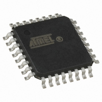
ATMEGA16U2-AUR Atmel, ATMEGA16U2-AUR Datasheet - Page 210

ATMEGA16U2-AUR
Manufacturer Part Number
ATMEGA16U2-AUR
Description
MCU AVR 8K FLASH 16MHZ 32TQFP
Manufacturer
Atmel
Series
AVR® ATmegar
Specifications of ATMEGA16U2-AUR
Core Processor
AVR
Core Size
8-Bit
Speed
16MHz
Connectivity
SPI, UART/USART, USB
Peripherals
Brown-out Detect/Reset, POR, PWM, WDT
Number Of I /o
22
Program Memory Size
16KB (8K x 16)
Program Memory Type
FLASH
Eeprom Size
512 x 8
Ram Size
512 x 8
Voltage - Supply (vcc/vdd)
2.7 V ~ 5.5 V
Oscillator Type
Internal
Operating Temperature
-40°C ~ 85°C
Package / Case
32-TQFP, 32-VQFP
Lead Free Status / RoHS Status
Lead free / RoHS Compliant
Data Converters
-
- Current page: 210 of 309
- Download datasheet (6Mb)
21.18.2
7799D–AVR–11/10
UDINT – USB Device Interrupt Register
• Bits 7:3 – Res: Reserved
These bits are reserved and will always read as zero.
• Bit 2 – RSTCPU: USB Reset CPU Bit
Writing this bit to one allows the CPU controller to reset the CPU when a USB bus reset condi-
tion is detected. When this mode is activated, the next USB bus reset event allows to reset the
CPU and all peripherals except the USB controller. This mode allows to perform a software
reset, but keep the USB device attached to the bus.
This bit is reset when the USB controller is disabled or when writing this bit to zero by firmware.
Writing this bit to zero makes the CPU system reset independent from the USB bus reset event.
• Bit 1 – RMWKUP: Remote Wake-up Bit
Writing this bit to one allows the USB controller to generate an “upstream-resume” packet on the
USB bus. This bit is immediately cleared by hardware and can not be read back to one. Writing
this bit to zero has no effect.
See
• Bit 0 – DETACH: Detach Bit
Writing this bit to one (default value) disables the USB D+ internal pull-up. This makes the USB
device controller physically “detached” from the USB bus. Writing this bit to zero enables the D+
internal pull-up and physically connects the USB device controller to the USB bus. See
on page 200
• Bit 7 – Res: Reserved
This bit is reserved and should always read as zero.
• Bit 6 – UPRSMI: Upstream Resume Interrupt Flag
This flag is set by hardware when the USB controller has successfully sent the Upstream
Resume sequence (See description of
UPRSME is set, the UPRSMI flag can generate a “USB general interrupt”. Writing this bit to zero
acknowledges the interrupt source (USB clocks must be enabled before). Writing this bit to one
has no effect.
• Bit 5 – EORSMI: End Of Resume Interrupt Flag
This flag is set by hardware when the USB controller detects an End Of Resume sequence on
the USB initiated by the host. If the EORSME bit is set, the EORSMI flag can generate a “USB
general interrupt”. Writing this bit to zero acknowledges the interrupt source (USB clocks must
be enabled before). Writing this bit to one has no effect.
Bit
(0xE1)
Read/Write
Initial Value
“Remote Wake-up” on page 201
for more details.
R
7
0
-
UPRSMI
R/W
6
0
EORSMI
R/W
5
0
for more details.
“Bit 1 – RMWKUP: Remote Wake-up Bit” on page
WAKEUPI
R/W
4
0
EORSTI
ATmega8U2/16U2/32U2
R/W
3
0
SOFI
R/W
2
0
R
1
0
-
SUSPI
R/W
0
0
“Detach”
210). If
UDINT
210
Related parts for ATMEGA16U2-AUR
Image
Part Number
Description
Manufacturer
Datasheet
Request
R

Part Number:
Description:
Manufacturer:
Atmel Corporation
Datasheet:

Part Number:
Description:
IC AVR MCU 16K 16MHZ 5V 44TQFP
Manufacturer:
Atmel
Datasheet:

Part Number:
Description:
IC AVR MCU 16K 16MHZ 5V 44-QFN
Manufacturer:
Atmel
Datasheet:

Part Number:
Description:
IC AVR MCU 16K 16MHZ 5V 40DIP
Manufacturer:
Atmel
Datasheet:

Part Number:
Description:
MCU AVR 16K FLASH 16MHZ 44-QFN
Manufacturer:
Atmel
Datasheet:

Part Number:
Description:
IC AVR MCU 16K 16MHZ COM 40-DIP
Manufacturer:
Atmel
Datasheet:

Part Number:
Description:
IC AVR MCU 16K 16MHZ COM 44-QFN
Manufacturer:
Atmel
Datasheet:

Part Number:
Description:
IC AVR MCU 16K 16MHZ IND 40-DIP
Manufacturer:
Atmel
Datasheet:

Part Number:
Description:
IC AVR MCU 16K 16MHZ IND 44-QFN
Manufacturer:
Atmel
Datasheet:

Part Number:
Description:
IC AVR MCU 16K 16MHZ IND 44-TQFP
Manufacturer:
Atmel
Datasheet:

Part Number:
Description:
IC MCU 8BIT 16KB FLASH 44TQFP
Manufacturer:
Atmel
Datasheet:

Part Number:
Description:
MCU AVR 16K FLASH 16MHZ 44-TQFP
Manufacturer:
Atmel
Datasheet:

Part Number:
Description:
IC AVR MCU 16K 16MHZ COM 44-TQFP
Manufacturer:
Atmel
Datasheet:


