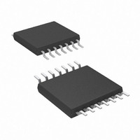
AT89LP214-20XU Atmel, AT89LP214-20XU Datasheet - Page 41

AT89LP214-20XU
Manufacturer Part Number
AT89LP214-20XU
Description
MCU 8051 2K FLASH 20MHZ 14-TSSOP
Manufacturer
Atmel
Series
89LPr
Datasheet
1.AT89LP213-20PU.pdf
(98 pages)
Specifications of AT89LP214-20XU
Core Processor
8051
Core Size
8-Bit
Speed
20MHz
Connectivity
SPI, UART/USART
Peripherals
Brown-out Detect/Reset, POR, PWM, WDT
Number Of I /o
12
Program Memory Size
2KB (2K x 8)
Program Memory Type
FLASH
Ram Size
128 x 8
Voltage - Supply (vcc/vdd)
2.4 V ~ 5.5 V
Oscillator Type
Internal
Operating Temperature
-40°C ~ 85°C
Package / Case
14-TSSOP
Package
14TSSOP
Device Core
8051
Family Name
AT89
Maximum Speed
20 MHz
Operating Supply Voltage
2.5|3.3|5 V
Data Bus Width
8 Bit
Number Of Programmable I/os
12
Interface Type
SPI/UART
Number Of Timers
2
Core
8051
Processor Series
AT89x
Maximum Clock Frequency
20 MHz
Data Ram Size
128 B
Mounting Style
SMD/SMT
Height
1.05 mm
Length
5.1 mm
Maximum Operating Temperature
+ 85 C
Minimum Operating Temperature
- 40 C
Supply Voltage (max)
5.5 V
Supply Voltage (min)
2.4 V
Width
4.5 mm
Lead Free Status / RoHS Status
Lead free / RoHS Compliant
Eeprom Size
-
Data Converters
-
Lead Free Status / Rohs Status
Details
17.2
17.2.1
3538E–MICRO–11/10
Baud Rates
Using Timer 1 to Generate Baud Rates
The baud rate in Mode 0 is fixed as shown in the following equation:
The baud rate in Mode 2 depends on the value of the SMOD1 bit in Special Function Register
PCON.7. If SMOD1 = 0 (the value on reset), the baud rate is 1/32 of the oscillator frequency. If
SMOD1 = 1, the baud rate is 1/16 of the oscillator frequency, as shown in the following equation:
The Timer 1 overflow rate determines the baud rates in Modes 1 and 3. When Timer 1 is the
baud rate generator, the baud rates are determined by the Timer 1 overflow rate and the value
of SMOD1 according to the following equation:
The Timer 1 interrupt should be disabled in this application. The Timer itself can be configured
for either timer or counter operation in any of its 3 running modes. In the most typical applica-
tions, it is configured for timer operation in auto-reload mode (high nibble of TMOD = 0010B). In
this case, the baud rate is given by the following formula:
Programmers can achieve very low baud rates with Timer 1 by configuring the Timer to run as a
16-bit auto-reload timer (high nibble of TMOD = 0001B). In this case, the baud rate is given by
the following formula.
Table 17-2
Table 17-2.
Mode 0: 1 MHz
Mode 2: 375K
Baud Rate
62.5K
19.2K
137.5
9.6K
4.8K
2.4K
1.2K
110
110
lists commonly used baud rates and how they can be obtained from Timer 1.
Commonly Used Baud Rates Generated by Timer 1 (TPS = 0000B)
Modes 1, 3
Modes 1, 3
Baud Rate
Baud Rate
Mode 2 Baud Rate
Modes 1, 3
Baud Rate
f
OSC
11.059
11.059
11.059
11.059
11.059
11.986
Mode 0 Baud Rate
12
12
12
(MHz)
2
6
=
=
2
------------------- -
2
------------------- -
=
SMOD1
SMOD1
32
32
2
------------------- -
SMOD1
=
32
SMOD1
×
×
2
------------------- -
SMOD1
X
0
1
1
0
0
0
0
0
0
0
Oscillator Frequency
------------------------------------------------------ -
Oscillator Frequency
------------------------------------------------------ -
[
32
256
=
×
[
(Timer 1 Overflow Rate)
Oscillator Frequency
------------------------------------------------------ -
256
–
×
(
RH1 RL1
(Oscillator Frequency)
–
(
TH1
C/T
,
X
X
0
0
0
0
0
0
0
0
0
2
)
]
)
]
×
×
AT89LP213/214
-------------------- -
TPS
-------------------- -
TPS
Mode
Timer 1
X
X
2
2
2
2
2
1
1
1
1
1
1
+
+
1
1
Reload Value
FEE0H
F55CH
F958H
F304H
DCH
DCH
B8H
F4H
70H
X
X
41


