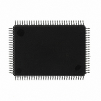
M30624FGAFP#U5 Renesas Electronics America, M30624FGAFP#U5 Datasheet - Page 477

M30624FGAFP#U5
Manufacturer Part Number
M30624FGAFP#U5
Description
IC M16C MCU FLASH 100QFP
Manufacturer
Renesas Electronics America
Series
M16C™ M16C/60r
Datasheets
1.M30622SAFPU5.pdf
(277 pages)
2.M30622SAFPU5.pdf
(617 pages)
3.M30622SAFPU5.pdf
(308 pages)
4.M30624FGAFPU5.pdf
(275 pages)
Specifications of M30624FGAFP#U5
Core Processor
M16C/60
Core Size
16-Bit
Speed
16MHz
Connectivity
SIO, UART/USART
Peripherals
DMA, PWM, WDT
Number Of I /o
85
Program Memory Size
256KB (256K x 8)
Program Memory Type
FLASH
Ram Size
20K x 8
Voltage - Supply (vcc/vdd)
4.2 V ~ 5.5 V
Data Converters
A/D 10x10b, D/A 2x8b
Oscillator Type
Internal
Operating Temperature
-20°C ~ 85°C
Package / Case
100-QFP
Cpu Family
M16C
Device Core Size
16/32Bit
Frequency (max)
16MHz
Interface Type
SIM/UART
Total Internal Ram Size
20KB
# I/os (max)
87
Number Of Timers - General Purpose
11
Operating Supply Voltage (typ)
5V
Operating Supply Voltage (max)
5.5V
Operating Supply Voltage (min)
4.2V
On-chip Adc
10-chx10-bit
On-chip Dac
2-chx8-bit
Instruction Set Architecture
CISC
Operating Temp Range
-20C to 85C
Operating Temperature Classification
Commercial
Mounting
Surface Mount
Pin Count
100
Package Type
PQFP
For Use With
867-1000 - KIT QUICK START RENESAS 62PM3062PT3-CPE-3 - EMULATOR COMPACT M16C/62P/30P
Lead Free Status / RoHS Status
Lead free / RoHS Compliant
Eeprom Size
-
Lead Free Status / Rohs Status
Compliant
Available stocks
Company
Part Number
Manufacturer
Quantity
Price
Part Number:
M30624FGAFP#U5M30624FGAFP#D3
Manufacturer:
Renesas Electronics America
Quantity:
10 000
Part Number:
M30624FGAFP#U5M30624FGAFP#D5
Manufacturer:
Renesas Electronics America
Quantity:
10 000
- M30622SAFPU5 PDF datasheet
- M30622SAFPU5 PDF datasheet #2
- M30622SAFPU5 PDF datasheet #3
- M30624FGAFPU5 PDF datasheet #4
- Current page: 477 of 617
- Download datasheet (9Mb)
2-158
Address Match Interrupt
2.12 Address Match Interrupt Usage
Figure 2.12.1. Unexecuted instructions and corresponding stacked addresses
2.12.1 Overview of the address match interrupt usage
The address match interrupt is used for correcting a ROM or for a simplified debugging-purpose monitor.
The following is an overview of the address match interrupt usage.
<Instructions whose address is added to by 2 when an address match interrupt occurs>
<Instructions whose address is added to by 1 when an address match interrupt occurs>
(1) Enabling/disabling the address match interrupt
(2) Timing of the address match interrupt
(3) Returning from an address match interrupt
(4) How to determine an address match interrupt
The address match interrupt enable bit can be used to enable and disable an address match interrupt.
It is affected neither by the processor interrupt priority level (IPL) nor the interrupt enable flag (I flag).
An interrupt occurs immediately before executing the instruction in the address indicated by the ad-
dress match interrupt register. Set the first address of the instruction in the address match interrupt
register. Setting a half address of an instruction or an address of tabulated data does not generate an
address match interrupt.
The first instruction of an interrupt routine does not generate an address match interrupt either.
The address put in the stack when an address match interrupt occurs depends on the instruction not
yet executed (the instruction the address match interrupt register indicates). The return address is not
put in the stack. For this reason, to return from an address match interrupt, either rewrite the content
of the stack and use the REIT instruction or use the POP instruction to restore the stack to the state as
it was before the interrupt occurred and return by use of a jump instruction.
Figure 2.12.1 shows unexecuted instructions and corresponding the stacked addresses.
Address match interrupts can be set at two different locations. However, both location will have the
same vector address. Therefore, it is necessary to determine which interrupt has occurred; address
match interrupt 0 or address match interrupt 1. Using the content of the stack, etc., determine which
interrupt has occurred according to the first part of the address match interrupt routine.
• 16-bit operation code instructions
• 8-bit operation code instructions given below
• Instructions other than those listed above
ADD.B:S
OR.B:S
STNZ.B:S
CMP.B:S
JMPS
MOV.B:S
#IMM8,dest
#IMM8,dest
#IMM8,dest
#IMM8,dest
#IMM8
#IMM,dest (However, dest = A0/A1)
SUB.B:S
MOV.B:S
STZX.B:S
PUSHM
JSRS
#IMM8,dest
#IMM8,dest
#IMM81,#IMM82,dest
src
#IMM8
SINGLE-CHIP 16-BIT CMOS MICROCOMPUTER
AND.B:S
STZ.B:S
POPM
M16C / 62A Group
Mitsubishi microcomputers
#IMM8,dest
#IMM8,dest
dest
Related parts for M30624FGAFP#U5
Image
Part Number
Description
Manufacturer
Datasheet
Request
R

Part Number:
Description:
KIT STARTER FOR M16C/29
Manufacturer:
Renesas Electronics America
Datasheet:

Part Number:
Description:
KIT STARTER FOR R8C/2D
Manufacturer:
Renesas Electronics America
Datasheet:

Part Number:
Description:
R0K33062P STARTER KIT
Manufacturer:
Renesas Electronics America
Datasheet:

Part Number:
Description:
KIT STARTER FOR R8C/23 E8A
Manufacturer:
Renesas Electronics America
Datasheet:

Part Number:
Description:
KIT STARTER FOR R8C/25
Manufacturer:
Renesas Electronics America
Datasheet:

Part Number:
Description:
KIT STARTER H8S2456 SHARPE DSPLY
Manufacturer:
Renesas Electronics America
Datasheet:

Part Number:
Description:
KIT STARTER FOR R8C38C
Manufacturer:
Renesas Electronics America
Datasheet:

Part Number:
Description:
KIT STARTER FOR R8C35C
Manufacturer:
Renesas Electronics America
Datasheet:

Part Number:
Description:
KIT STARTER FOR R8CL3AC+LCD APPS
Manufacturer:
Renesas Electronics America
Datasheet:

Part Number:
Description:
KIT STARTER FOR RX610
Manufacturer:
Renesas Electronics America
Datasheet:

Part Number:
Description:
KIT STARTER FOR R32C/118
Manufacturer:
Renesas Electronics America
Datasheet:

Part Number:
Description:
KIT DEV RSK-R8C/26-29
Manufacturer:
Renesas Electronics America
Datasheet:

Part Number:
Description:
KIT STARTER FOR SH7124
Manufacturer:
Renesas Electronics America
Datasheet:

Part Number:
Description:
KIT STARTER FOR H8SX/1622
Manufacturer:
Renesas Electronics America
Datasheet:

Part Number:
Description:
KIT DEV FOR SH7203
Manufacturer:
Renesas Electronics America
Datasheet:


