M30624FGAFP#U5 Renesas Electronics America, M30624FGAFP#U5 Datasheet - Page 365
M30624FGAFP#U5
Manufacturer Part Number
M30624FGAFP#U5
Description
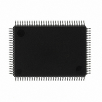
IC M16C MCU FLASH 100QFP
Manufacturer
Renesas Electronics America
Series
M16C™ M16C/60r
Datasheets
1.M30622SAFPU5.pdf
(277 pages)
2.M30622SAFPU5.pdf
(617 pages)
3.M30622SAFPU5.pdf
(308 pages)
4.M30624FGAFPU5.pdf
(275 pages)
Specifications of M30624FGAFP#U5
Core Processor
M16C/60
Core Size
16-Bit
Speed
16MHz
Connectivity
SIO, UART/USART
Peripherals
DMA, PWM, WDT
Number Of I /o
85
Program Memory Size
256KB (256K x 8)
Program Memory Type
FLASH
Ram Size
20K x 8
Voltage - Supply (vcc/vdd)
4.2 V ~ 5.5 V
Data Converters
A/D 10x10b, D/A 2x8b
Oscillator Type
Internal
Operating Temperature
-20°C ~ 85°C
Package / Case
100-QFP
Cpu Family
M16C
Device Core Size
16/32Bit
Frequency (max)
16MHz
Interface Type
SIM/UART
Total Internal Ram Size
20KB
# I/os (max)
87
Number Of Timers - General Purpose
11
Operating Supply Voltage (typ)
5V
Operating Supply Voltage (max)
5.5V
Operating Supply Voltage (min)
4.2V
On-chip Adc
10-chx10-bit
On-chip Dac
2-chx8-bit
Instruction Set Architecture
CISC
Operating Temp Range
-20C to 85C
Operating Temperature Classification
Commercial
Mounting
Surface Mount
Pin Count
100
Package Type
PQFP
For Use With
867-1000 - KIT QUICK START RENESAS 62PM3062PT3-CPE-3 - EMULATOR COMPACT M16C/62P/30P
Lead Free Status / RoHS Status
Lead free / RoHS Compliant
Eeprom Size
-
Lead Free Status / Rohs Status
Compliant
Available stocks
Company
Part Number
Manufacturer
Quantity
Price

Part Number:
M30624FGAFP#U5M30624FGAFP#D3
Manufacturer:
Renesas Electronics America
Quantity:
10 000
Part Number:
M30624FGAFP#U5M30624FGAFP#D5
Manufacturer:
Renesas Electronics America
Quantity:
10 000


Timer B
2-46
Operation
Note
Figure 2.3.8. Operation timing of pulse period measurement mode
2.3.4 Operation of Timer B (pulse period measurement mode)
In pulse period/pulse width measurement mode, choose functions from those listed in Table 2.3.3. Op-
erations of the circled items are described below. Figure 2.3.8 shows the operation timing, and Figure
2.3.9 shows the set-up procedure.
Measurement pulse
Count start flag
Count source
Reload register
transfer timing
Timing at which counter
reaches “0000
Timer Bi interrupt
request bit
Timer Bi overflow flag
Measurement of pulse time interval from falling edge to falling edge
Table 2.3.3. Choosed functions
(1) Setting the count start flag to “1” causes the counter to start counting the count source.
(2) If a measurement pulse changes from “H” to “L”, the value of the counter goes to “0000
(3) If a measurement pulse changes from “H” to “L” again, the value of the counter is transferred
• The timer Bi interrupt request bit goes to “1” when an effective edge of a measurement pulse is
• The value of the counter at the beginning of a count is indeterminate. Therefore, the timer Bi
• The timer Bi overflow flag is indeterminate after reset. The timer Bi overflow flag goes to “0” if
Count source
Measurement
mode
input or timer Bi is overflowed. The factor of interrupt request can be determined by use of the
timer Bi overflow flag within the interrupt routine.
overflow flag may go to “1” and timer Bi interrupt request may be generated during the interval
between a count start and an effective edge input.
timer Bi mode register is written to when the count start flag is “1”. This flag cannot be set to “1”
by software.
and measurement is started. In this instance, an indeterminate value is transferred to the
reload register. The timer Bi interrupt request does not generate.
to the reload register, and the timer Bi interrupt request bit goes to “1”. Then the value of the
counter becomes “0000
16
Item
Note 1: Counter is initialized at completion of measurement.
Note 2: Timer has overflowed.
”
counter
O
O
“H”
“0”
“1”
“L”
“1”
“0”
“1”
“0”
Internal count source (f
Pulse period measurement (interval between measurement pulse falling edge to falling edge)
Pulse period measurement (interval between measurement pulse rising edge to rising edge)
Pulse width measurement (interval between measurement pulse falling edge to rising edge,
(1) Start count
16
”, and the measurement is started again.
Cleared to “0” when interrupt request is accepted, or cleared by software
(Note 1)
1
/ f
8
and between rising edge to falling edge)
/ f
(2) Start measurement
32
/ fc
Transfer
(indeterminate value)
32
)
Set-up
(Note 1)
SINGLE-CHIP 16-BIT CMOS MICROCOMPUTER
(3) Start measurement again
Transfer
(measured value)
(Note 2)
M16C / 62A Group
Mitsubishi microcomputers
16
”,
Related parts for M30624FGAFP#U5
Image
Part Number
Description
Manufacturer
Datasheet
Request
R

Part Number:
Description:
KIT STARTER FOR M16C/29
Manufacturer:
Renesas Electronics America
Datasheet:

Part Number:
Description:
KIT STARTER FOR R8C/2D
Manufacturer:
Renesas Electronics America
Datasheet:

Part Number:
Description:
R0K33062P STARTER KIT
Manufacturer:
Renesas Electronics America
Datasheet:

Part Number:
Description:
KIT STARTER FOR R8C/23 E8A
Manufacturer:
Renesas Electronics America
Datasheet:

Part Number:
Description:
KIT STARTER FOR R8C/25
Manufacturer:
Renesas Electronics America
Datasheet:

Part Number:
Description:
KIT STARTER H8S2456 SHARPE DSPLY
Manufacturer:
Renesas Electronics America
Datasheet:

Part Number:
Description:
KIT STARTER FOR R8C38C
Manufacturer:
Renesas Electronics America
Datasheet:

Part Number:
Description:
KIT STARTER FOR R8C35C
Manufacturer:
Renesas Electronics America
Datasheet:

Part Number:
Description:
KIT STARTER FOR R8CL3AC+LCD APPS
Manufacturer:
Renesas Electronics America
Datasheet:
Part Number:
Description:
KIT STARTER FOR RX610
Manufacturer:
Renesas Electronics America
Datasheet:

Part Number:
Description:
KIT STARTER FOR R32C/118
Manufacturer:
Renesas Electronics America
Datasheet:

Part Number:
Description:
KIT DEV RSK-R8C/26-29
Manufacturer:
Renesas Electronics America
Datasheet:

Part Number:
Description:
KIT STARTER FOR SH7124
Manufacturer:
Renesas Electronics America
Datasheet:

Part Number:
Description:
KIT STARTER FOR H8SX/1622
Manufacturer:
Renesas Electronics America
Datasheet:

Part Number:
Description:
KIT DEV FOR SH7203
Manufacturer:
Renesas Electronics America
Datasheet: