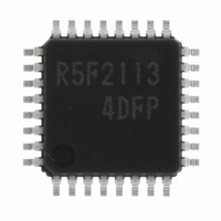
R5F21134DFP#U0 Renesas Electronics America, R5F21134DFP#U0 Datasheet - Page 5

R5F21134DFP#U0
Manufacturer Part Number
R5F21134DFP#U0
Description
IC R8C MCU FLASH 32LQFP
Manufacturer
Renesas Electronics America
Series
M16C™ M16C/R8C/Tiny/13r
Datasheets
1.R5F211A2SPU0.pdf
(300 pages)
2.R5F21132FPU0.pdf
(33 pages)
3.R5F21132FPU0.pdf
(226 pages)
4.R5F21134DFPU0.pdf
(224 pages)
Specifications of R5F21134DFP#U0
Core Size
16-Bit
Program Memory Size
16KB (16K x 8)
Oscillator Type
Internal
Core Processor
R8C
Speed
20MHz
Connectivity
SIO, UART/USART
Peripherals
LED, POR, Voltage Detect, WDT
Number Of I /o
22
Program Memory Type
FLASH
Ram Size
1K x 8
Voltage - Supply (vcc/vdd)
2.7 V ~ 5.5 V
Data Converters
A/D 12x10b
Operating Temperature
-40°C ~ 85°C
Package / Case
32-LQFP
No. Of I/o's
22
Eeprom Memory Size
4KB
Ram Memory Size
1024Byte
Cpu Speed
20MHz
No. Of Timers
16
Digital Ic Case
RoHS Compliant
Controller Family/series
R8C/13
Rohs Compliant
Yes
Lead Free Status / RoHS Status
Lead free / RoHS Compliant
For Use With
R0K521134S000BE - KIT EVAL STARTER FOR R8C/13R0E521134EPB00 - KIT EMULATOR PROBE FOR PC7501R0E521134CPE00 - EMULATOR COMPACT R8C/13
Eeprom Size
-
Lead Free Status / RoHS Status
Lead free / RoHS Compliant
Available stocks
Company
Part Number
Manufacturer
Quantity
Price
Part Number:
R5F21134DFP#U0R5F21134DFP
Manufacturer:
Renesas Electronics America
Quantity:
10 000
- R5F211A2SPU0 PDF datasheet
- R5F21132FPU0 PDF datasheet #2
- R5F21132FPU0 PDF datasheet #3
- R5F21134DFPU0 PDF datasheet #4
- Current page: 5 of 226
- Download datasheet (3Mb)
1.
2.
This hardware manual provides detailed information on the R8C/13 Group of microcomputers.
Users are expected to have basic knowledge of electric circuits, logical circuits and microcomputers.
The symbols, and descriptions, used for bit function in each register are shown below.
*1
*2
*3
*4
*5
Blank:Set to “0” or “1” according to the application
0: Set to “0”
1: Set to “1”
X: Nothing is assigned
RW: Read and write
RO: Read only
WO: Write only
Follow the text in each manual for binary and hexadecimal notations.
Reserved bit
Nothing is assigned
Do not set to this value
Function varies depending on mode of operation
: Nothing is assigned
Introduction
Register Diagram
Reserved bit. Set to specified value.
Nothing is assigned to the bit concerned. As the bit may be use for future functions,
set to “0” when writing to this bit.
The operation is not guaranteed when a value is set.
Bit function varies depending on peripheral function mode.
Refer to respective register for each mode.
X X X r e g i s t e r
b 7
b 6
How to Use This Manual
b 5
b 4
b 3
0
b 2
b 1
b 0
B i t s y m b o l
X X X 0
X X X 1
X X X 4
X X X 5
X X X 6
X X X 7
( b 2 )
( b 3 )
S y m b o l
X X X
*1
N o t h i n g i s a s s i g n e d .
W h e n w r i t e , s h o u l d s e t t o " 0 " . W h e n r e a d , i t s c o n t e n t i s i n d e t e r m i n a t e .
X X X B i t
X X X B i t
X X X B i t
R e s e r v e d B i t
B i t N a m e
A d d r e s s
X X X
b 1 b 0
1 0 : X X X
0 1 : X X X
1 0 : A v o i d t h i s s e t t i n g
1 1 : X X X
0 : X X X
1 : X X X
F u n c t i o n v a r i e s d e p e n d i n g o n e a c h
o p e r a t i o n m o d e
M u s t s e t t o “ 0 ”
A f t e r r e s e t
0 0
h
F u n c t i o n
*5
R W
R W
R W
W O
R W
R W
R W
R O
*3
*4
*2
Related parts for R5F21134DFP#U0
Image
Part Number
Description
Manufacturer
Datasheet
Request
R

Part Number:
Description:
KIT STARTER FOR M16C/29
Manufacturer:
Renesas Electronics America
Datasheet:

Part Number:
Description:
KIT STARTER FOR R8C/2D
Manufacturer:
Renesas Electronics America
Datasheet:

Part Number:
Description:
R0K33062P STARTER KIT
Manufacturer:
Renesas Electronics America
Datasheet:

Part Number:
Description:
KIT STARTER FOR R8C/23 E8A
Manufacturer:
Renesas Electronics America
Datasheet:

Part Number:
Description:
KIT STARTER FOR R8C/25
Manufacturer:
Renesas Electronics America
Datasheet:

Part Number:
Description:
KIT STARTER H8S2456 SHARPE DSPLY
Manufacturer:
Renesas Electronics America
Datasheet:

Part Number:
Description:
KIT STARTER FOR R8C38C
Manufacturer:
Renesas Electronics America
Datasheet:

Part Number:
Description:
KIT STARTER FOR R8C35C
Manufacturer:
Renesas Electronics America
Datasheet:

Part Number:
Description:
KIT STARTER FOR R8CL3AC+LCD APPS
Manufacturer:
Renesas Electronics America
Datasheet:

Part Number:
Description:
KIT STARTER FOR RX610
Manufacturer:
Renesas Electronics America
Datasheet:

Part Number:
Description:
KIT STARTER FOR R32C/118
Manufacturer:
Renesas Electronics America
Datasheet:

Part Number:
Description:
KIT DEV RSK-R8C/26-29
Manufacturer:
Renesas Electronics America
Datasheet:

Part Number:
Description:
KIT STARTER FOR SH7124
Manufacturer:
Renesas Electronics America
Datasheet:

Part Number:
Description:
KIT STARTER FOR H8SX/1622
Manufacturer:
Renesas Electronics America
Datasheet:

Part Number:
Description:
KIT DEV FOR SH7203
Manufacturer:
Renesas Electronics America
Datasheet:


